Fire damper BKP-EN
Technical documentation
Installation in lightweight partition walls with metal posts
Construction subject to change.
No return possible!
Version: 2020-09-01 | Page 16
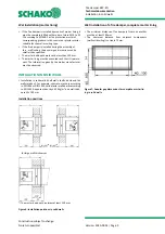
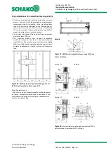
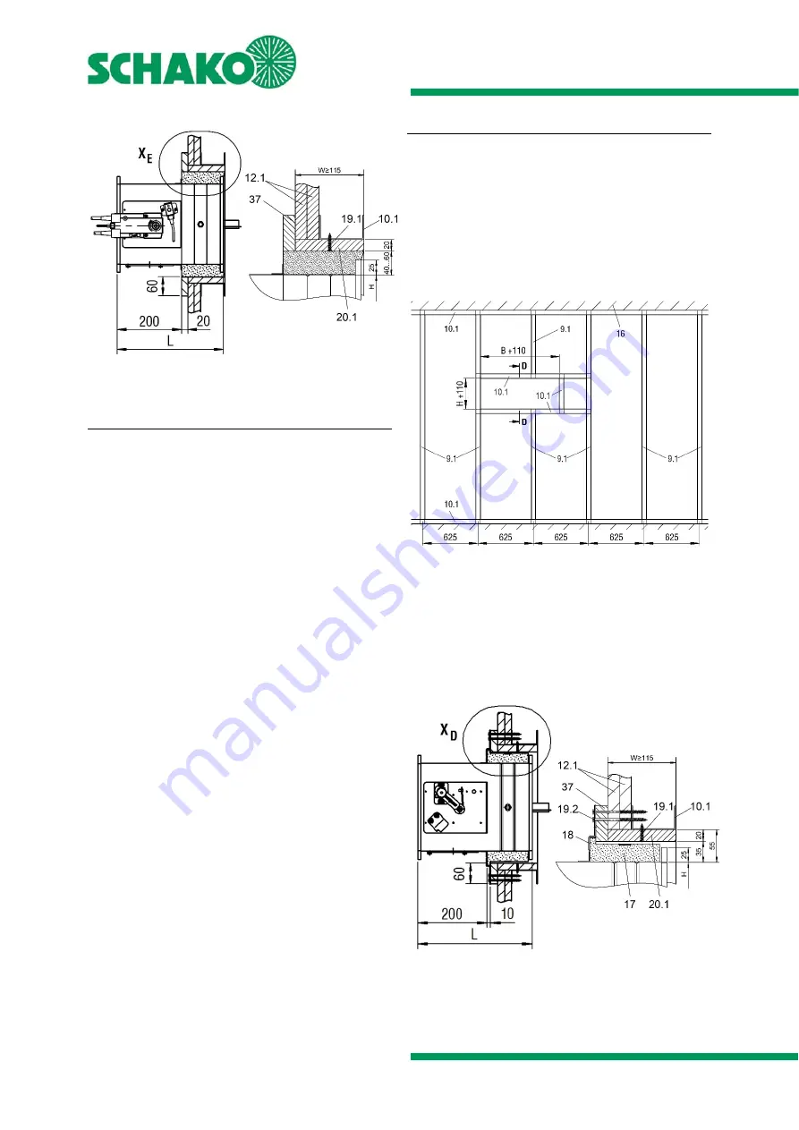
Section E-E
Detail X
E
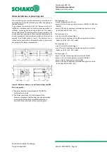
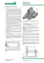
Figure 20: Wall panelling and double-board layers
(shaft wall)
Installation procedure
Mount the metal posts and the wall in accordance with the
specifications of the wall manufacturer and the required ex-
change parts as shown on Figure 19.
Construct a circumferential reveal (pos 20.1) with 20 mm
plasterboards and screw them centrally to the circumferen-
tial metal profile frame (pos. 19.1 - fastening: e.g. drywall
screws ø 3.5 x 35 mm, screw distance ≤ 250 mm, but at least
2 screws per side).
Insert the BKP-EN into the wall recess (operating side - ob-
serve the installation dimension of 200 mm). Average out
the circumferential annular gap evenly between the wall
and the BKP-EN. Mount the BKP-EN with the help of
mounting suspensions, etc.
Insert mortar (pos. 13; mortar bed depth at least 130 mm)
into the circumferential annular gap between the housing
of the BKP-EN and the circumferential reveal (pos. 20.1).
Mounting aids (suspension, wedges, etc.) must be removed
(fixing lugs are no installation and mounting aids and must
remain mounted).
10.1 Profile UW 75/40/0.6 - 150 profiles
12.1 Panelling (on one side 2x20) of the shaft wall made of
gypsum-bonded wall boards.
19.1 Drywall screws (on site, e.g. ø 3.5 x 35 mm)
20.1 Reveal, circumferential (on site, 20 mm plasterboards)
37 Double-board layer (gypsum-bonded wall boards, d=20
mm, b=60 mm). Fastening: Dry-wall screws, for example,
ø 5.5 x 90, a ≤ 200 mm, but at least 2 screws per side,
connection and butt joints of the double-board layer
must be filled with the wall material.
Dry installation of a fire damper
•
Dry installation in a shaft wall panelled on one side is
only possible for BKP-EN with installation frame ER-P1.
•
The minimum distance between the fire dampers must
be at least 200 mm.
•
The minimum distance from adjacent components must
be at least 110 mm from the wall and 100 mm from the
solid ceiling. The actual minimum distance may slightly
differ from the distances mentioned above and must be
executed and adapted as a function of the wall connec-
tion type.
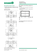
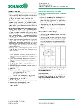
Figure 21: Metal posts plus required exchange parts for dry
installation with installation frame ER-P1
Mounting information: In the overlap area of the exchangea-
ble profiles, they must be riveted, crimped or screwed once
on both sides. These connections are purely for fastening the
individual metal profiles during mounting.
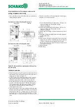
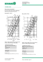
Section D-D
Detail X
D
Figure 22: Dry installation with installation frame ER-P1 in
shaft wall

