Fire damper BKP-EN
Technical documentation
Service
Construction subject to change.
No return possible!
Version: 2020-09-01 | Page 38
SERVICE
FUNCTIONAL CHECKING, CLEANING, REPAIR
Polluted and damp air can impair the continuous operational
safety. Therefore, after commissioning of the ventilation in-
stallation, the function of all fire dampers must be checked
semiannually. If two consecutive functional checks do not
show any defects, the fire dampers only have to be tested
once a year. If maintenance are made for ventilation systems,
it is recommended including the functional checks of the fire
dampers in these agreements.
Information on explosion-protected release devices can be
found in the additional operating instructions according to
ATEX 2014/34/EU.
1. Manual trigger device
1.1. Visual inspection
Check the fire damper for damage and contamination
(e.g. housing, damper blade, seals).
Perform necessary cleaning work
1.2 Manual release - Closing the fire damper
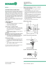
Pull manual unlocking disc (pos. 25) at the hand lever
(pos. 3), this removes the locking (in the open position)
of the locking bolt (pos. 27) in the trigger device
(pos. 5).
Hand lever has been released and is moved toward the
CLOSED position by spring force.
ATTENTION!
Do not reach into the pivoting range of the damper blade and
of the manual lever. There is a significant risk of injury.
The fire damper must close and lock automatically (lock-
ing of the damper blade in the CLOSED position).
1.3 Opening the fire damper
Pull manual unlocking disc (pos. 25) at the hand lever
(pos. 3) and move it toward the trigger device (pos. 5)
Locking bolt (pos. 27) must snap into the release device
(pos. 5).
The fire damper is ready for operation again (damper
blade is locked in the OPEN position).
S = Lubricate moving parts (bearing) only if they are not run-
ning smoothly (lubricant: free of resin and acid).
When the fusible link becomes damaged, its replacement
must be carried out as follows.
If, for example, the fusible link is damaged or corroded, it
is must be replaced.
Perform manual release as described in section 1.2.
Unscrew the fastening screws (2 pieces, pos.26), pull the
release device out by turning it 90° and remove it from the
housing.
Compress the locating pins of the fusible link holder (pos.
28) using a suitable tool (e.g. pliers) and replace the fusi-
ble link with a replacement fusible link (pos. 6).
Insert the release device and fasten it with screws (make
sure that the position of the coding screw with regard to
the coding hole is correct).
Finally a functional check has to be carried out.
BKP-EN with manual trigger
Figure 42: Side view BKP-EN (manual release)
Figure 43: Front view BKP-EN (manual release)
Figure 44: Release device BKP-EN (fusible link)


