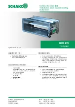
Fire damper BKP-EN
Technical documentation
Models and dimensions
Construction subject to change.
No return possible!
Version: 2020-09-01 | Page 5
Available sizes [mm]
Width (B)
Height (H)
100
100
150
125
200
150
250
160
300
175
400
200
500
225
600
250
700
800
Table 1: Available sizes
Housing length L = 330 mm.
All heights and widths which can be combined
are available!
Trigger device always on H side
Inspection opening always on B side (bottom)
Intermediate sizes on request
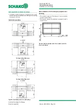
Frame bores
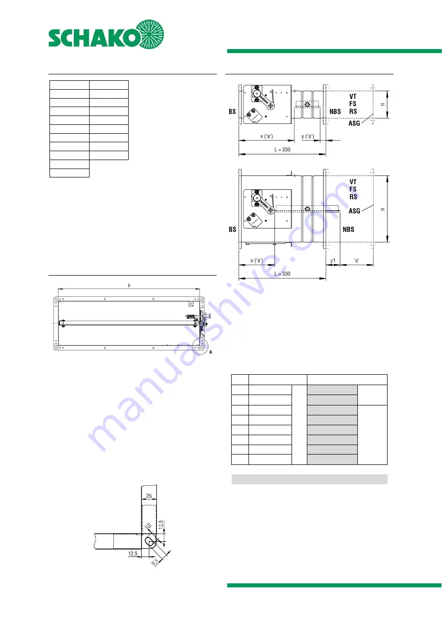
Figure 2: Frame bores
The fire damper type BKP-EN is supplied with front side fitted
corner long holes for M8 screws. The connection flanges of
the B sides are provided with additional fastening holes from
width B ≥ 200 mm (centre position for B ≥ 200 mm up
to B < 600 and 1/3 position for width ≥ 600 mm).
On the non-operating side, either fastening materials (e.g.
screws, press-in nuts, etc.) must be provided and attached for
mounting duct components prior to installation or, alterna-
tively, extension pieces (on site or as accessories, e.g. SCHAKO
type VT) can be mounted.
Detail A
Figure 3: Detail A - Corner angle
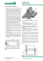
Damper blade projecting ends
Figure 4: Damper blade projecting ends
"a" = 50 mm: Minimum distance between the front edge of
the open damper blade and the finishing protective grating
(ASG), the flexible spigot (FS) or the duct connection spigot
(RS).
SCHAKO
ASG/VT/FS/RS:
Flange
holes
suitable
for
BKP-EN
H
Operating side (BS)
Non-operating side (NBS)
100
210
x
20 *
y
125
198
8 *
150
185
5 *
y1
160
180
10 *
175
173
18 *
200
160
30 *
225
148
43 *
250
135
55 *
* Extension piece (VT) necessary
Table 2: Damper blade projecting ends

