Fire damper BKP-EN
Technical documentation
Models and dimensions
Construction subject to change.
No return possible!
Version: 2020-09-01 | Page 8
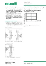
Minimum distances or projecting ends
The dimensions given must be considered an installation rec-
ommendation for the BKP-EN and may differ, depending on
the local situation.
To guarantee fire protection, the fire damper must be in-
stalled in accordance with the technical documentation, in-
stallation, mounting and operating instructions. The inspec-
tion opening of the fire damper must be freely accessible, oth-
erwise inspection openings in the connected ventilation ducts
must be provided in the immediate proximity. This must be
ensured in particular when at least 2 fire dampers are in-
stalled next to each other or below each other in the immedi-
ate proximity of adjacent components.
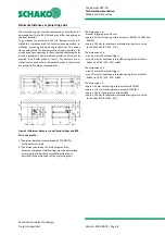
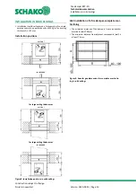
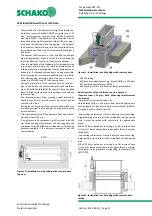
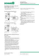
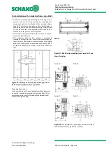
Figure 5: Minimum distances to walls and ceilings and BKP-
EN to one another
1.) Minimum distance recommended by SCHAKO for
sufficient accessibility
2.) The distance between the fire damper and the
adjacent component (wall/ceiling) must be determined
according to the particular installation situation or
adjusted to the dimensions of the projecting ends.
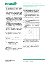
The dimension x is:
- manual trigger approx. 60 mm
- approx. 90 mm for spring return actuators B10/B11 or B42 and
S00/S01
- approx. 185 mm for explosion-protected spring return actua-
tor Ex-Max-5.10-BF (X10 - X15)
The dimension y1 is:
- max. 65 mm with manual trigger
- max. 40 mm for explosion-protected spring return actuator
Ex-Max-5.10-BF (X10 - X15) or B42
The dimension y2 is:
- max. 25 mm with manual trigger
- max. 40 mm for explosion-protected spring return actuator
Ex-Max-5.10-BF (X10 - X15) or B42
The dimension z is:
- approx. 95 mm with spring return actuators B10/B11
- approx. 110 mm for spring return actuators S00/S01
- approx. 135 for spring return actuator B42
- approx. 160 mm for explosion-protected spring return actua-
tor Ex-Max-5.10-BF (X10 - X15)

