Fire damper BSK-RPR-EU
Technical documentation
Spring return actuators
Construction subject to change
No return possible
Version: 2021-07-01 | Page 15
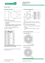
Spring return actuators S00/S01
S00
(GRA126.1E/SO3)/
S01
(GRA326.1E/SO2)
Figure 17: BSK-RPR-EU with spring return actuator S00/S01
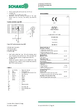
LED functions
Figure 18: LED functions of spring return actuators S00/S01
Attention!
Safety function is only guaranteed if the actuator has been
connected to the supply voltage in accordance with regula-
tions and unlocked mechanically.
Cable designation
Table 9: Cable designation S00/S01
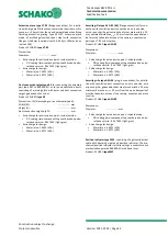
Connection diagram
Spring return actuator S00 (
24V AC/ 24…48V DC)
Figure 19: Connection diagram S00
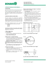
Connection diagram
Spring return actuator S01 (230V AC)
Figure 20: Connection diagram S01
The wires are colour-coded and labelled.
Connection
Cable
Meaning
Code
No.
Colour
Abbreviation
Drives
G
1
red
RD
System potential AC 24 V/DC 24…48 V
AC 24 V
G0
2
black
BK
System zero
DC 24…48 V
Drives
L
3
brown
BN
Phase AC 230 V
AC 230 V
N
4
blue
BU
Zero conductor
Auxiliary switch
Q11
S1
grey/red
GYRD
Switch A (“CLOSED”) input
Q12
S2
grey/blue
GYBU
Switch A (“CLOSED”) rest contact
Q14
S3
grey/pink
GYPK
Switch A (“CLOSED”) NO contact
Q21
S4
black/red
BKRD
Switch B (“OPEN”) input
Q22
S5
black/blue
BKBU
Switch B (“OPEN”) rest contact
Q24
S6
black/pink
BKPK
Switch B (“OPEN”) NO contact
○ red =
operating voltage OK
Thermal sensor defective
○ green = operating voltage OK
Thermal sensor OK
● dark =
no operating voltage
AC 24 V
DC 24…48 V
(SELV/PELV)
AC 230 V


