


Installation, Mounting and Maintenance DISA-W
Z11/27 - 5
Construction subject to change.
No return possible!
20.10.2015
Version:
Installation and commissioning
Operating conditions
Prior to installation or commissioning of the device, the follow-
ing operating conditions must be observed:
Material reception
Upon reception of the materials, the components must be care-
fully checked, in order to guarantee that no transport damage
has taken place. Moreover, the dimensions, composition and
number of the identification sticker must be checked as to
whether they are as ordered.
Identification sticker:
To prevent possible damage during transport, the devices will
be delivered ex works on pallets (that correspond to the partic-
ular weight and dimensions) wrapped with tapes and transpar-
ent plastic film. It is recommended leaving this protection in
place until the device is commissioned. The openings of the
pipes should be closed with dust caps to avoid dust and entry of
dirt.
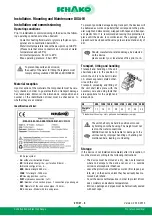
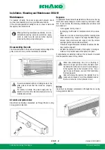
Transport, lifting and handling
Transport and handling of the unit
shall take place in the position in
which the unit is to be built in later
on, unless expressly stated other-
wise on the unit.
Transport, unloading and lifting of
the unit shall take place with the
necessary care and using tools that
are appropriate for the weight and
dimensions.
(1)
Standard unit: h slot + grille and heat exchanger (empty)
Storage
If the device is not installed immediately after its reception, it
must be stored according to the following instructions:
- Coolant or heating fluid: water or glycols (ethylene or pro-
pylene) at a concentration below 60%.
- Water inlet temperature: above the dew point up to 80°C
(Please note that some connectors do not work at water
temperatures above 65°C)
- Air inlet temperature: from 2 to 45°C
- Max. operating pressure: 8 bar / 95°C
-
H:
2-pipe system
-
OL:
without air deflection blades
-
SR:
Perforated sheet grille, - perforation Ø 6 mm -
-
A:
Nozzle configuration - A -
-
900:
Nominal
length 900 mm -
-
1200
: Total length -1200 mm-
-
M:
Housing position - centre -
-
WS1
: Hydraulic connection - left -
-
AS1:
Number of connection pipes - 1 connection pipe arranged
-
123:
Diameter of the connection pipes - 123 mm -
-
2E:
End piece - Model with two end pieces-
To prevent deposits and corrosion,
the quality of the water for filling the registers must
comply with regulations VDI 2035 and DIN 50930.
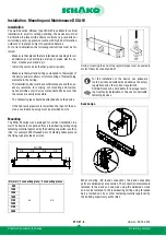
NL
900 1200 1500 1800 2100 2400 2700 3000
Weights
(1)
(kg)
11
14
17
20
23
27
30
33
- The device must be stored at a dry, clean, safe location
where no damage to the device can occur, i.e., outside
corrosive atmospheric influences.
- Leave the protections attached ex works (film, tapes, pal-
lets, etc.) on the device, unless they have already been re-
moved beforehand.
- Cover the device with tarpaulins, in order to protect it from
dust, moisture and extreme temperatures.
- Entries, openings and pipes must be hermetically sealed
with dust caps.
Should manufacture-related damage be detected
on the device,
please contact your local sales office prior to in-
The unit shall only be held in position or moved
by holding on to the housing. The weight must not
rest on the water connections.
SCHAKO cannot be held liable for damage to the
unit caused by improper handling or handling not
mentioned here, loading or unloading.