
Installation, Mounting and Maintenance DISA-W
Z11/27 - 6
Construction subject to change.
No return possible!
20.10.2015
Version:
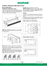
Installation
The wall induction diffuser type DISA-W is suitable for vertical
installation in a wall or ceiling panelling. The devices must not
be installed in places with extreme moisture (e.g. laundries or
swimming pools), aggressive media, with high dust formation,
outdoors or in places subject to explosion hazards.
For correct installation, the following instructions must be fol-
lowed:
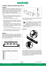
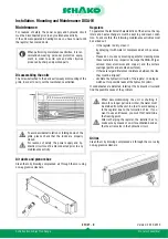
Mounting
The DISA-W series was developed for vertical installation in a
wall. The device is suspended from a load-bearing ceiling using
fastening material approved by the building supervisory author-
ities, for example M6 threaded bars. Fastening takes place on
the fixing lugs provided ex works.
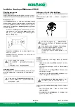
During mounting the end of the register pipes must be sealed to
protect them from dust and dirt.
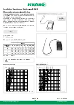
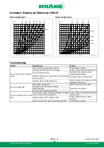
Band design
When ordering -BV (band connection), the band connection
parts are delivered as accessories. The connection elements are
fastened to the device on one side using the delivered screws
and can be fastened to the load-bearing ceiling using threaded
bars provided on site or other fastening material approved by
the building supervisory authorities.
- Make sure that places that are intended as openings for air
admission and air discharge are free of pipes, electric ca-
bles, crossbeams, stands, etc.
- Install the unit at a site that has good air quality.
- Make sure that wall and ceiling correspond to the weight of
the device and also allow correct mounting of the fastening
elements in the ceiling.
- The installation site must have sufficient space and the nec-
essary resources for carrying out mounting and mainte-
nance activities of all device components. Make sure that
the valves are easily accessible.
- The hydraulic pipes should be attached above the device.
- If the hydraulic pipework is lower than the input of the de-
vice, a ventilation opening must be provided on site.
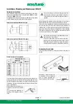
NL (mm) 1 connecting piece 2 connecting pieces
900
a,c
a,b
1200
1500
1800
2100
2400
2700
3000
a
c
b
c
a
NL-155
1/4
1/4
115
1/4
1/4
For the installation of the device, use adequate
tools, devices and materials and observe the safety
regulations and other current regulations.
SCHAKO cannot be held liable for damage result-
ing from faulty installation or the use of unsuitable
fastening devices.
A
A
B
B