

Installation, Mounting and Maintenance DISA-W
Z11/27 - 7
Construction subject to change.
No return possible!
20.10.2015
Version:
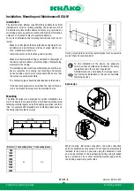
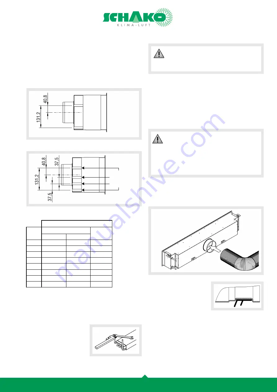
Hydraulic connections
Upon customer request, the hydraulic connection to the regis-
ters can be established either on the left-hand (-
WS1
) or right-
hand side (-
WS2
) of the unit.
As standard the cooling circuit pipes are attached on the outside
and the heating circuits at the centre of the register.
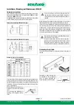
Hydraulic connections DISA-W-H (2-pipe)
Hydraulic connections DISA-W-HT (4-pipe)
Amount of water of the registers:
The connection of the hydraulic connections can be done by sol-
dering, pressing (in connection with supporting sleeves) or by
means of flexible hoses resistant to oxygen diffusion and push-
fit systems. The use of flexible hoses is subject to the manufac-
turer's specification.
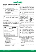
When making the hydraulic con-
nections, you have to use suitable
tools
to avoid excessive tightening or
twisting of the register connec-
tions.
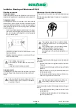
When charging the register, make sure by means of on-site ven-
tilation devices that no air remains in the hydraulic circuit.
If the unit is to be installed at a location having temperatures be-
low zero degrees, glycol must be admixed to the coolant in a
suitable ratio, to ensure that the freezing point of this liquid al-
ways stays below the minimum temperature of the operating
site. Please note that the use of an antifreeze necessarily results
in a loss in performance of the register.
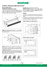
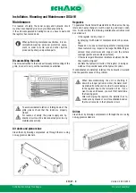
Connecting the air ducts
The air ducts are attached by using pipe clamps, fixing lugs or
the like.
Optionally, a rubber lip seal can
be installed on the connection
pipe, to ensure tightness be-
tween the device and the pipes.
Water capacity
(litres)
NL
DISA-W-HT
DISA-W-H
Heating
Cooling
900
0,2
0,6
0,8
1200
0,3
0,8
1
1500
0,3
1
1,3
1800
0,4
1,2
1,6
2100
0,5
1,4
1,8
2400
0,5
1,6
2,1
2700
0,6
1,8
2,4
3000
0,7
2
2,7
Heating Coolin
g
In order to achieve a uniform cooling capacity, the
wall induction diffusers type DISA-W should be
connected to the cold water distribution system in
parallel.
The wall induction diffusers type DISA-W are induc-
tion devices for "dry cooling".
To avoid condensation, the cold water supply tem-
perature must be selected such that it does not fall
below the dew point, which may make it necessary
to install protective devices (condensate monitors).


