11
2019-05-24 / V1.0
Contactors C137/C163/C164/C165 – Installation and Maintenance Instructions
Product information
SPST-NO contactor C163 C
C
A
B
D
D
A
E
A
B
C
C
A
B
D
D
A
E
A
B
C
F
G
H
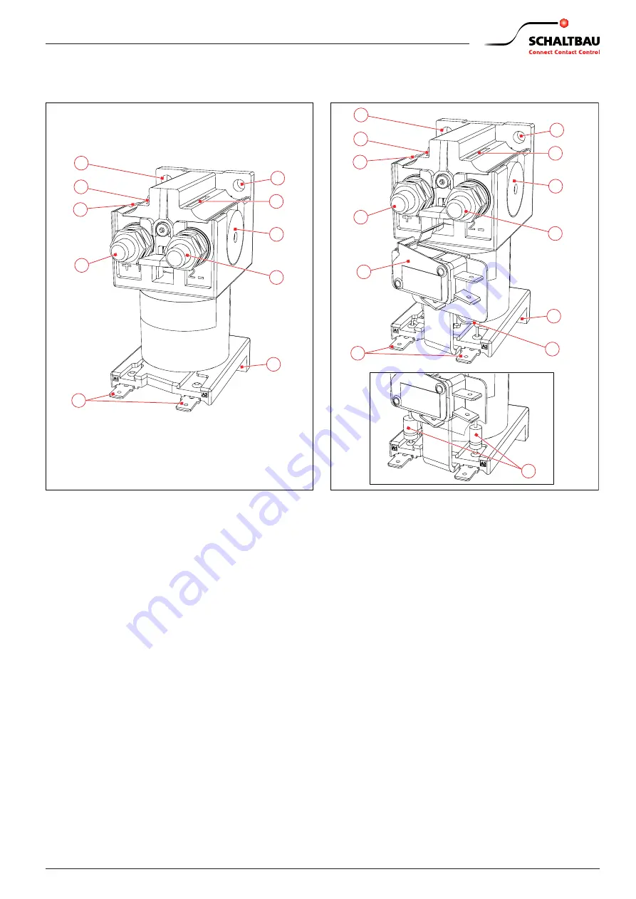
Fig. 5:
SPST-NO contactor C163 C, standard version
A Mounting holes for screws M5, Tightening torque: 6 Nm
B Plasma exits
C Permanent magnets
D Main contacts, normally open contact (make), designed
to make and break current like an open style power relay,
Terminals: M8, Tightening torque: max. 6 Nm
E Coil terminals A1 and A2, Flat tabs 6.3 x 0.8 mm
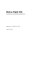
Fig. 6:
SPST-NO Contactor C163 C, fitted with auxiliary
contact (F) and varistor (G) or diodes (H)
A Mounting holes for screws M5, Tightening torque: 6 Nm
B Plasma exits
C Permanent magnets
D Main contacts, normally open contact (make), designed
to make and break current like an open style power relay,
Terminals: M8, Tightening torque: max. 6 Nm
E Coil terminals A1 and A2, Flat tabs 6.3 x 0.8 mm
F Auxiliary contact (1x microswitch, S840),
Terminals: Flat tabs 6.3 x 0.8 mm
G Coil suppression with varistor
H Coil suppression with diodes


