21
2019-05-24 / V1.0
Contactors C137/C163/C164/C165 – Installation and Maintenance Instructions
Installation
Installation on the bottom side
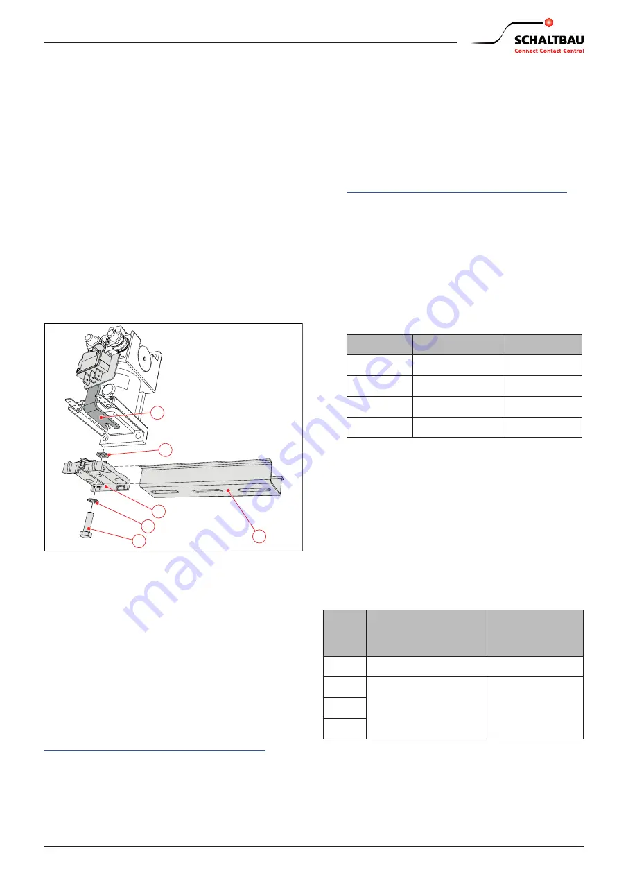
X
Loosen the hexagon screw (9) at the bottom side
of the contactor.
X
Place the spacer sleeve (10) between the angled
mounting bracket (11) of the auxiliary contact and
the DIN rail adapter (4).
X
Slightly fasten the DIN rail adapter (4) with the
hexagon screw (9) and washer (8).
X
Adjust the angled mounting bracket (11) of the
auxiliary contact.
-
Ensure safe switching of the auxiliary contact!
X
Tighten the hexagon screw (9) with a torque of 2
Nm.
X
Attach the installed contactor with the DIN rail
adapter (4) to the DIN rail (7).
10
7
9
8
4
11
Fig. 21: DIN rail mounting: Installation on the bottom side
(the figure shows C163, the procedure for C137, C164
and C165 is the same)
7.2 Electrical installation
Electrical data and further technical
specifications
For the power consumption of the magnetic drive sys-
tem and electrical data of the auxiliary switches refer
to the respective data sheets and to our catalogue
B60
.
The catalogue is available under:
https://www.schaltbau.com/en/media-library/
Preliminaries
X
The connection of the main current circuit can be
done with wires or busbars.
X
The minimum gauges of the wires/busbars must
be observed. For the required cross sections of
wires/busbars refer to our catalogue
B60
.
The catalogue is available under:
https://www.schaltbau.com/en/media-library/
X
If wires are used, the wire gauges must be selected
in coordination with their insulation class and the
operating conditions.
X
Depending on the contactor type the wires of the
main current circuit must be fitted with appropri-
ate cable lugs (for terminal nuts M6, M8 or M10)
X
The terminal nuts for the main contacts and the
maximum permissible torque for the different
contactor series are determined as follows:
Series
Terminal nuts
Torque
C137
M6
max. 3 Nm
C163
M8
max. 6 Nm
C164
M8
max. 6 Nm
C165
M10
max. 10 Nm
X
In order to secure the terminal nuts against self-
loosening, appropriate screw locking elements
have to be provided. Schaltbau recommends
Schnorr-Washers (or similar) to secure the nuts.
The terminal nuts against must be tightened with
the determined torque (refer to the table above).
X
The terminals of the coil and the auxiliary contact
are designed as flat tabs. Therefore the control
wires must be fitted with appropriate flat recep-
tacles for tabs. Depending on the series, the table
shows the type of flat receptacles.
Series
Auxiliary contact
terminals:
flat receptacles for tabs
Coil terminals:
flat receptacles for
tabs
C137
A 2.8 x 0.5 mm
A 6.3 x 0.8 mm
C163
A 6.3 x 0.8 mm
A 6.3 x 0.8 mm
C164
C165
X
The maximum permissible cross section of the
auxiliary contact control cables is 1 mm
2
/ AWG 18
stranded wire.


