User Manual, Power contactors, series CT1115/08 and CT1130/08
Rev. 2.2
Page 10/26
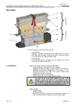
Auxiliary contact group (AG)
Standard:
- 1 contact to indicate the “well closed” position of the main con-
tacts (EN60077: a1)
- 1 contact to indicate the “well opened” position of the main con-
tacts (EN60077: b0)
- 2 NO/NC contacts
Option:
- 4 NO/NC contacts
- M3 screw or 6.3 x 0.8 mm fast-on terminals
- Protection cap (can be removed and fixed only when the Upper
Module has been removed)
Coil terminal group (TG)
- Cage clamp terminals
- Protection cap (can be removed and fixed only when the Upper
Module has been removed; fixation with screw M4 x 10)
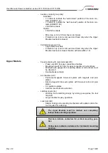
Upper Module
Fixed contacts with main terminals (FC)
- Press nuts M10 for easy connection of cables
- Mounting hole Ø 12.7 mm for easy connection of current bars
- Minimum wire gauges for connecting cables or current bars must
be observed.
- Double-break contacts
Arc chamber (AC)
- Permanent-magnetic blow-out system with magnets and pole
plates
- Electro-magnetic blow-out system with blow-out coils and pole
plates
- Arc guidance plates
- Ceramic inserts for arc extinction
Latching levers (LL)
- Latching and unlatching simply by turning pole plates. No tool
required.
- Large handles for easy operation.
Lock bars (LB)
- Simple locking and unlocking mechanism with optical control. No
tool required for unlocking.
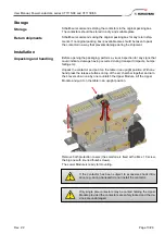
The Upper Module must be latched and completely
locked before starting operation.
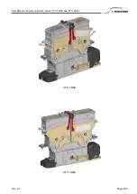
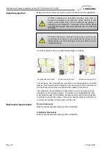
Red bars indicate contactors for vertical mounting posi-
tion
Yellow bars indicate contactors for horizontal mounting
position.

