User Manual, Power contactors, series CT1115/08 and CT1130/08
Rev. 2.2
Page 14/26
Operating position
Make sure that you have received the correct contactors for the application.
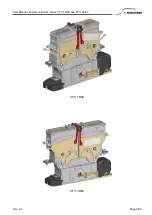
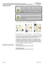
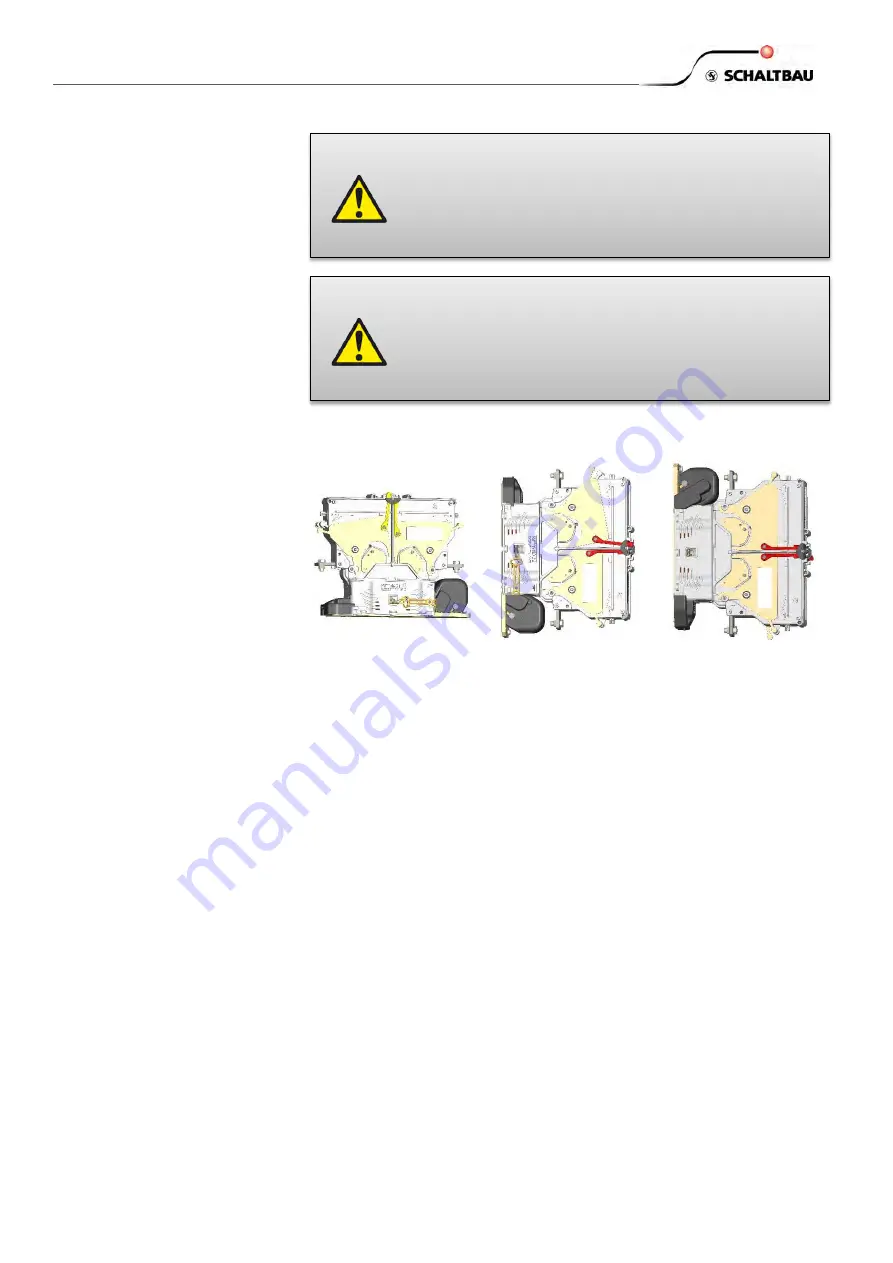
CT1000 contactors can be mounted horizontally or vertically.
Horizontal mounting position
Vertical mounting position 1
Vertical mounting position 2
In most cases, the contactors are mounted on mounting plates or mounting
frames. They must be solid enough to carry the weight of the contactors un-
der the shock and vibration conditions of the railway environment.
The contactors (Lower Module) are fixed with 4 or more mounting screws,
depending on the number of poles. The screws (and if applicable the nuts)
must be steel grade 8.8. Schaltbau strongly recommends Schnorr-Washers
(or similar) to secure the screws. The screws must be tightened with the rat-
ed torque permissible for the screws and the nuts.
Mechanical requirements
Device dimensions
Refer to the dimensioned drawings of the contactors.
Installation dimensions
Refer to the dimensioned drawings of the contactors.
CT1000 contactors for horizontal mounting must only be
mounted horizontally (Lock bars are yellow, position is also
shown on the labels); they can be mounted in any position in
reference to the direction of movement of the vehicle. Make
sure that both Upper and Lower Module are for horizontal
mounting.
CT1000 contactors for vertical mounting must only be mount-
ed vertically (Lock bars are red, position is also shown on the
labels). Make sure that both Upper and Lower Module are for
vertical mounting.

