Firmware Design
P746/EN FD/G31
MiCOM P746
(FD) 9-
5
All modules are connected by a parallel data and address bus that allows the processor
board to send and receive information to and from the other modules as required. There is
also a separate serial data bus for conveying sample data from the input module to the
processor.
Note: It is possible to connect to the Ethernet network any of the P746 without the embedded
Ethernet board using the RS485 to Ethernet converter MiCOM I4X (Courier protocol)
1.2 Software
overview
The busbar protection is a centralised system.
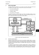
The software for the relay can be conceptually split into four elements; the real-time
operating system, the system services software, the platform software and the protection
and control software. These four elements are not distinguishable to the user, and are all
processed. The distinction between the four parts of the software is made purely for the
purpose of explanation here:
Control of interfaces to keypad,
LCD, LEDs, Front & Rear comm. ports
Sample data,
Logic inputs &
Outputs contacts
Measurements & event,
fault & disturbance records
Protection &
control settings
Protection & Control software
Platform software
Disturbance
recorder task
Programmable &
fixed scheme logic
Signal processing &
saturation detection
Protection
algorithms
Topology
algorithms
Front panel interface
(LCD & Keypad)
Local & remote
communications
interface - Courier
Event, Fault,
Disturbance,
Maintenance
record logging.
Settings
database
System services software
Relay hardware
P3704ENb
FIGURE 2: SOFTWARE OVERVIEW
FD
1.2.1
Real-time operating system
As explain in the hardware overview, each relay contains one main board. A real time
operating system is used to provide a framework for the different parts of the relay’s software
to operate within. To this end the software is split into tasks. The real-time operating system
is responsible for scheduling the processing of these tasks such that they are carried out in
the time available and in the desired order of priority.
The real-time operating system is responsible for scheduling the processing of these tasks
such that they are carried out in the time available and in the desired order of priority. The
operating system is also responsible for the exchange of information between tasks, in the
form of messages.
Summary of Contents for MiCOM P746
Page 4: ......
Page 5: ...Pxxx EN SS G11 SAFETY SECTION...
Page 6: ......
Page 8: ...Pxxx EN SS G11 Page 2 8 Safety Section BLANK PAGE...
Page 16: ...P746 EN IT G31 Introduction MiCOM P746...
Page 18: ...P746 EN IT G31 Introduction IT 1 2 MiCOM P746 IT BLANK PAGE...
Page 26: ...P746 EN TD G31 Technical Data MiCOM P746...
Page 38: ...P746 EN GS G31 Getting Started MiCOM P746...
Page 78: ...P746 EN ST G31 Getting Started MiCOM P746...
Page 80: ...P746 EN ST G31 Settings ST 4 2 MiCOM P746 ST BLANK PAGE...
Page 112: ...P746 EN ST G31 Settings ST 4 34 MiCOM P746 ST BLANK PAGE...
Page 114: ...P746 EN OP G31 Operation MiCOM P746...
Page 136: ...P746 EN OP G31 Operation OP 5 22 MiCOM P746 OP BLANK PAGE...
Page 138: ...P746 EN AP G31 Application Notes MiCOM P746...
Page 142: ...P746 EN AP G31 Application Notes AP 6 4 MiCOM P746 AP BLANK PAGE...
Page 194: ...P746 EN AP G31 Application Notes AP 6 56 MiCOM P746 AP BLANK PAGE...
Page 196: ...P746 EN PL G31 Programmable Logic MiCOM P746...
Page 238: ...P746 EN MR A11 Measurements and Recording MiCOM P746...
Page 240: ...P746 EN MR A11 Measurements and Recording MR 8 2 MiCOM P746 MR BLANK PAGE...
Page 258: ...P746 EN FD G31 Firmware Design MiCOM P746...
Page 280: ......
Page 348: ...P746 EN MT A11 Maintenance MiCOM P746...
Page 350: ...P746 EN MT A11 Maintenance MT 11 2 MiCOM P746 MT BLANK PAGE...
Page 364: ...P746 EN MT A11 Maintenance MT 11 16 MiCOM P746 MT BLANK PAGE...
Page 366: ...P746 EN TS G31 Troubleshooting MiCOM P746...
Page 368: ...P746 EN TS G31 Troubleshooting TS 12 2 MiCOM P746 TS BLANK PAGE...
Page 382: ...P746 EN SC G31 SCADA Communications MiCOM P746...
Page 424: ...P746 EN SC G31 SCADA Communications SC 13 42 MiCOM P746 SC BLANK PAGE...
Page 426: ...P746 EN SG F21 Symbols and Glossary MiCOM P746...
Page 438: ......
Page 440: ...P746 EN IN G31 Installation IN 15 2 MiCOM P746 IN BLANK PAGE...
Page 468: ......
Page 470: ...P746 EN HI G31 Remote HMI HI 16 2 MiCOM P746 HI BLANK PAGE...
Page 500: ...P746 EN HI G31 Remote HMI HI 16 32 MiCOM P746 HI BLANK PAGE...
Page 502: ......
Page 504: ...P746 EN CS A11G31 Cyber Security CS 17 2 MiCOM P746 CS BLANK PAGE...
Page 524: ...P746 EN VH G31 Firmware and Service Manual Version History MiCOM P746...
Page 529: ......


