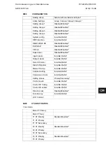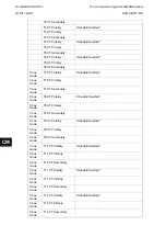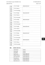
P746/EN CM/F21
Commissioning and Maintenance
(CM) 10-26
MiCOM P746
For all characteristics, allowance must be made for the accuracy of the test equipment being
used.
Characteristic
Operating time at twice current setting and time
multiplier/time dial setting of 1.0
Nominal (seconds)
Range (seconds)
DT
[:
Ι
>1 Time Delay] setting
Setting ±2%
IEC S Inverse
10.03
9.53 – 10.53
IEC V Inverse
13.50
12.83 – 14.18
IEC E Inverse
26.67
24.67 – 28.67
UK LT Inverse
120.00
114.00 – 126.00
IEEE M Inverse
0.64
0.61 – 0.67
IEEE V Inverse
1.42
1.35 – 1.50
IEEE E Inverse
1.46
1.39 – 1.54
US Inverse
0.46
0.44 – 0.49
US ST Inverse
0.26
0.25 – 0.28
TABLE 6: CHARACTERISTIC OPERATING TIMES FOR
Ι
>1
Re-perform the tests for the function I>2.
Upon completion of the tests any current differential, overcurrent, earth fault, breaker fail or
supervision elements which were disabled for testing purposes must have their original
settings restored in the CONFIGURATION column.
6.2.3
Breaker Failure Protection
CM
6.2.3.1
Separate external 50BF protection to the busbar protection
Feeder 1
Feeder 2
Coupler
Feeder 3
Feeder 4
P3751ENb
CB Fail
External Fault
For example as shown in the above figure, we simulate a CB fail in feeder 1. Therefore, we
energise the opto input “External CB Fail” of the feeder1 and we check that the P746 issues
a tripping order to feeder 2 and the coupler.
The trip of the backup phase overcurrent or earth fault overcurrent protection initiates, as
described above, the timers tBF3 and tBF4.
Summary of Contents for MiCOM P746
Page 4: ......
Page 5: ...Pxxx EN SS G11 SAFETY SECTION...
Page 6: ......
Page 8: ...Pxxx EN SS G11 Page 2 8 Safety Section BLANK PAGE...
Page 16: ...P746 EN IT G31 Introduction MiCOM P746...
Page 18: ...P746 EN IT G31 Introduction IT 1 2 MiCOM P746 IT BLANK PAGE...
Page 26: ...P746 EN TD G31 Technical Data MiCOM P746...
Page 38: ...P746 EN GS G31 Getting Started MiCOM P746...
Page 78: ...P746 EN ST G31 Getting Started MiCOM P746...
Page 80: ...P746 EN ST G31 Settings ST 4 2 MiCOM P746 ST BLANK PAGE...
Page 112: ...P746 EN ST G31 Settings ST 4 34 MiCOM P746 ST BLANK PAGE...
Page 114: ...P746 EN OP G31 Operation MiCOM P746...
Page 136: ...P746 EN OP G31 Operation OP 5 22 MiCOM P746 OP BLANK PAGE...
Page 138: ...P746 EN AP G31 Application Notes MiCOM P746...
Page 142: ...P746 EN AP G31 Application Notes AP 6 4 MiCOM P746 AP BLANK PAGE...
Page 194: ...P746 EN AP G31 Application Notes AP 6 56 MiCOM P746 AP BLANK PAGE...
Page 196: ...P746 EN PL G31 Programmable Logic MiCOM P746...
Page 238: ...P746 EN MR A11 Measurements and Recording MiCOM P746...
Page 240: ...P746 EN MR A11 Measurements and Recording MR 8 2 MiCOM P746 MR BLANK PAGE...
Page 258: ...P746 EN FD G31 Firmware Design MiCOM P746...
Page 280: ......
Page 348: ...P746 EN MT A11 Maintenance MiCOM P746...
Page 350: ...P746 EN MT A11 Maintenance MT 11 2 MiCOM P746 MT BLANK PAGE...
Page 364: ...P746 EN MT A11 Maintenance MT 11 16 MiCOM P746 MT BLANK PAGE...
Page 366: ...P746 EN TS G31 Troubleshooting MiCOM P746...
Page 368: ...P746 EN TS G31 Troubleshooting TS 12 2 MiCOM P746 TS BLANK PAGE...
Page 382: ...P746 EN SC G31 SCADA Communications MiCOM P746...
Page 424: ...P746 EN SC G31 SCADA Communications SC 13 42 MiCOM P746 SC BLANK PAGE...
Page 426: ...P746 EN SG F21 Symbols and Glossary MiCOM P746...
Page 438: ......
Page 440: ...P746 EN IN G31 Installation IN 15 2 MiCOM P746 IN BLANK PAGE...
Page 468: ......
Page 470: ...P746 EN HI G31 Remote HMI HI 16 2 MiCOM P746 HI BLANK PAGE...
Page 500: ...P746 EN HI G31 Remote HMI HI 16 32 MiCOM P746 HI BLANK PAGE...
Page 502: ......
Page 504: ...P746 EN CS A11G31 Cyber Security CS 17 2 MiCOM P746 CS BLANK PAGE...
Page 524: ...P746 EN VH G31 Firmware and Service Manual Version History MiCOM P746...
Page 529: ......


