P746/EN SC/G31
SCADA Communications
(SC) 13-
30
MiCOM
P746
SC
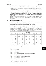
Since the range of the data type is only 100 years, the century must be deduced. The
century is calculated as the one that will produce the nearest time value to the current date.
For example: 30-12-99 is 30-12-1999 when received in 1999 & 2000, but is 30-12-2099
when received in 2050. This technique allows 2 digit years to be accurately converted to 4
digits in a ±50 year window around the current datum.
The invalid bit has two applications:
1.
It can indicate that the date-time information is considered inaccurate, but is the best
information
available.
2.
Date-time information is not available.
The summertime bit is used to indicate that summertime (day light saving) is being used and,
more importantly, to resolve the alias and time discontinuity which occurs when summertime
starts and ends. This is important for the correct time correlation of time stamped records.
The day of the week field is optional and if not calculated will be set to zero.
The concept of time zone is not catered for by this data type and hence by the relay. It is up
to the end user to determine the time zone utilized by the relay. Normal practice is to use
UTC (universal co-ordinated time), which avoids the complications with day light saving
time-stamp correlation’s.
3.9
Power & energy measurement data formats (G29 & G125)
The power and energy measurements are available in two data formats; G29 integer format
and G125 IEEE754 floating point format. For historical reasons the registers listed in the
main part of the “Measurements 2” column of the menu database (see P746/EN MD) are of
the G29 format. The floating point, G125, versions appear at the end of the column.
3.9.1
Data type G29
Data type G29 consists of three registers. The first register is the per unit power or energy
measurement and is of type G28, which is a signed 16 bit quantity. The second and third
registers contain a multiplier to convert the per unit value to a real value. The multiplier is of
type G27, which is an unsigned 32-bit quantity. Thus, the overall value conveyed by the G29
data type must be calculated as G29 = G28
×
G27.
The relay calculates the G28 per unit power or energy value as G28 = ((measured
secondary quantity)/(CT secondary)
×
(110V/(VT secondary)). Since data type G28 is a
signed 16-bit integer, its dynamic range is constrained to ±32768. This limitation should be
borne in mind for the energy measurements, as the G29 value will saturate a long time
before the equivalent G125 does.
The associated G27 multiplier is calculated as G27 = (CT primary)
×
(VT primary/110V)
when primary value measurements are selected, and as G27 = (CT secondary)
×
(VT
secondary/110V) when secondary value measurements are selected.
Due to the required truncations from floating point values to integer values in the calculations
of the G29 component parts and its limited dynamic range, the use of the G29 values is only
recommended when the MODBUS master cannot deal with the G125 IEEE754 floating point
equivalents.
Note that the G29 values must be read in whole multiples of three registers. It is not
possible to read the G28 and G27 parts with separate read commands.
Example:
For A-Phase Power (Watts) (registers 30300 - 30302) for a 110V relay, In = 1A,
VT ratio = 110V:110V and CT ratio = 1A:1A.
Applying A-phase 1A @ 63.51V
A-phase Watts = ((63.51V
×
1A)/In = 1A)
×
(110/Vn = 110V) = 63.51 Watts
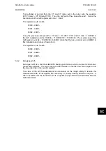
The G28 part of the value is the truncated per unit quantity, which will be equal to 64 (40h).
Summary of Contents for MiCOM P746
Page 4: ......
Page 5: ...Pxxx EN SS G11 SAFETY SECTION...
Page 6: ......
Page 8: ...Pxxx EN SS G11 Page 2 8 Safety Section BLANK PAGE...
Page 16: ...P746 EN IT G31 Introduction MiCOM P746...
Page 18: ...P746 EN IT G31 Introduction IT 1 2 MiCOM P746 IT BLANK PAGE...
Page 26: ...P746 EN TD G31 Technical Data MiCOM P746...
Page 38: ...P746 EN GS G31 Getting Started MiCOM P746...
Page 78: ...P746 EN ST G31 Getting Started MiCOM P746...
Page 80: ...P746 EN ST G31 Settings ST 4 2 MiCOM P746 ST BLANK PAGE...
Page 112: ...P746 EN ST G31 Settings ST 4 34 MiCOM P746 ST BLANK PAGE...
Page 114: ...P746 EN OP G31 Operation MiCOM P746...
Page 136: ...P746 EN OP G31 Operation OP 5 22 MiCOM P746 OP BLANK PAGE...
Page 138: ...P746 EN AP G31 Application Notes MiCOM P746...
Page 142: ...P746 EN AP G31 Application Notes AP 6 4 MiCOM P746 AP BLANK PAGE...
Page 194: ...P746 EN AP G31 Application Notes AP 6 56 MiCOM P746 AP BLANK PAGE...
Page 196: ...P746 EN PL G31 Programmable Logic MiCOM P746...
Page 238: ...P746 EN MR A11 Measurements and Recording MiCOM P746...
Page 240: ...P746 EN MR A11 Measurements and Recording MR 8 2 MiCOM P746 MR BLANK PAGE...
Page 258: ...P746 EN FD G31 Firmware Design MiCOM P746...
Page 280: ......
Page 348: ...P746 EN MT A11 Maintenance MiCOM P746...
Page 350: ...P746 EN MT A11 Maintenance MT 11 2 MiCOM P746 MT BLANK PAGE...
Page 364: ...P746 EN MT A11 Maintenance MT 11 16 MiCOM P746 MT BLANK PAGE...
Page 366: ...P746 EN TS G31 Troubleshooting MiCOM P746...
Page 368: ...P746 EN TS G31 Troubleshooting TS 12 2 MiCOM P746 TS BLANK PAGE...
Page 382: ...P746 EN SC G31 SCADA Communications MiCOM P746...
Page 424: ...P746 EN SC G31 SCADA Communications SC 13 42 MiCOM P746 SC BLANK PAGE...
Page 426: ...P746 EN SG F21 Symbols and Glossary MiCOM P746...
Page 438: ......
Page 440: ...P746 EN IN G31 Installation IN 15 2 MiCOM P746 IN BLANK PAGE...
Page 468: ......
Page 470: ...P746 EN HI G31 Remote HMI HI 16 2 MiCOM P746 HI BLANK PAGE...
Page 500: ...P746 EN HI G31 Remote HMI HI 16 32 MiCOM P746 HI BLANK PAGE...
Page 502: ......
Page 504: ...P746 EN CS A11G31 Cyber Security CS 17 2 MiCOM P746 CS BLANK PAGE...
Page 524: ...P746 EN VH G31 Firmware and Service Manual Version History MiCOM P746...
Page 529: ......


