SCHEMPP-HIRTH FLUGZEUGBAU GmbH., KIRCHHEIM/TECK
Ventus-2cM
FLIGHT MANUAL
November
2003
Revision --
7.12.3
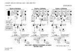
BATTERY - WIRING DIAGRAM - AVIONIC
M03 RE 832/2
Main switch
AVIONIC
Selector
switch
Rotary
multipoint
switch
*)
Parts listed on page 7.12.4
E-
Va
ri
o
Lo
g
g
er
Di
o
d
e
E-
Va
ri
o
Lo
g
g
er
Di
o
d
e
V
U
J
R
E
E
E
E
E
I
B
a
tt
. A
v
io
ni
c /
12
V
/
7-
7.
2A
h
B
a
tt
. E
ngi
ne
12
V
/
2 x 7.
2
A
h
12
V
/
16
-1
8
A
h
12
V
/
28
A
h
Cha
rging
soc
k
et
Op
ti
o
n
Cha
rging
soc
k
et
6.
3
A
2A
4A
6.
3
A
2A
6.
3
A
2A
4A
6.
3
A
2A
6.
3
A
2A
6.3A
E
Selector switch
J
Main switch
ENGINE
H
Main switch
AVIONIC
I
6.3A
E
Main switch
ENGINE
H
W
W
4A
S
tan
dar
d C
h
ar
g
in
g
sock
et
S
T
S
T
B
a
tt
. E
ngi
ne
12
V
/
2 x 7.
2
A
h
12
V
/
16
-1
8
A
h
12
V
/
28
A
h
2A
S
tan
dar
d C
h
ar
h
in
g
sock
et
Selector
switch
J
S
T
S
T
K
K
V
U
V
U
V
U
V
U
Main switch
AVIONIC
Selector
switch
E-
Va
ri
o
Lo
g
g
er
Di
o
d
e
J
E
I
B
a
tt
. E
ngi
ne
12
V
/
2 x 7.
2
A
h
12
V
/
16
-1
8
A
h
12
V
/
28
A
h
Cha
rging
soc
k
et
6.
3
A
4A
6.3A
E
Main switch
ENGINE
H
W
4A
S
tan
dar
d
Cha
rhing
s
o
c
k
e
t
S
T
S
T
K
to engine
managment
system
B
a
tt
. A
v
io
ni
c /
12
V
/
7-
7.
2A
h
B
a
tt
. A
v
io
ni
c /
12
V
/
7-
7.
2A
h
OPTION - SOLAR
Re
g
u
la
to
r
O
n
e or
mo
re
so
la
r pa
ne
ls
Version - 2 Batteries
Battery installation in accordance with position of CG
Version - 3 Batteries
Battery installation in accordance with position of CG
Version - 4 Batteries
Battery installation in accordance with position of CG
Selector switch
for 2 batteries
Rotary multip. switch
for 3 or 4 batteries
Solar panels to be
wired at the main
power supply only
by regulator with
V
max
= 13.8V !
OPTION
Electrolytic capacitor as a
voltage buffer for Logger / E-Vario
Electr.
capacitor
22000µF
25V
Other additional equipment
to be wired in compliance
with the manufacturer's
instructions and be fused
individually.
Option
Low voltage
indicator
OPTION
Electrolytic capacitor as a
voltage buffer for Logger / E-Vario
Other additional equipment
to be wired in compliance
with the manufacturer's
instructions and be fused
individually.
Electr.
capacitor
22000µF
25V
Option
Low voltage
indicator
to engine
managment
system
to engine
managment
system
Option
Low voltage
indicator
Other additional equipment
to be wired in compliance
with the manufacturer's
instructions and be fused
individually.
OPTION
Electrolytic capacitor as a
voltage buffer for Logger / E-Vario
Electr.
capacitor
22000µF
25V
Cha
rging
soc
k
et
Op
ti
o
n
Cha
rging
soc
k
et
OPTION
SOLAR
OPTION
SOLAR
Summary of Contents for Ventus-2cM
Page 11: ......

