damaged.
•
The tractor must have a flow connection
and a load-free return connection.
•
Ensure proper connection of the hoses.
•
Hydraulic hoses shall be stored in the inten-
ded repository.
Operation with PTO
•
Before connecting the machine to the
three-point hitch of the tractor, make sure
that the weight of machine is within the
tractor’s specifications. The weight of the
machine can be found on the manufacturer
type plate
•
Make sure that the machine is connected
correctly to the three-point hitch and that
the safety bolts are always in place. The
upper link only in higher hole. The lower
hole is for the driving devise.
•
When working, be careful in order to pre
-
vent accidents or damages.
•
Only connect the drive shaft only to the
engine of the tractor when it is not running.
•
Use only drive shafts that are approved and
suitable for the use with the log splitter.
Furthermore the drive shaft must be equip
-
ped with all safety mechanisms, which
must be in good condition.
•
Keep away from the drive shaft when it is
in use.
•
Make sure that the shaft speed of the trac
-
tor does not exceed the value specified on
the type plate (max 300 rpm).
•
It is recommended to wear earplugs or
equivalent hearing protection.
•
Do not operate the machine indoors. The
exhaust fumes are harmful to health. They
can cause unconsciousness and there-
fore pose a threat to the operator. If it is
necessary to work indoors or in covered
surroundings, make sure that there is suf
-
ficient ventilation. Do not inhale the exhaust
fumes!
Modifications of any kind to the machine are
prohibited!
•
For specific instructions regarding the drive
shaft, refer to its user manual (delivered
with the drive shaft).
•
For maintenance work or if the splitting
wedge is stuck, disconnect the machine
from the tractor first, after stopping the
tractor.
Never leave the machine unattended while it
is still connected to the power source!
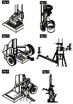
Using the log lifter
General information on the log lifter:
•
The log lifter is ready for operation
•
If not used, the log lifter must be in the up
-
per position. (Insert the hitch pins in the top
hole;
Fig.9 „A“
) It can then be used as a
second protection handle preventing lateral
displacement of the log.
•
For safety reasons, only the last link of
the log lifter‘s chain will be attached to
the suspension plate.
•
Make sure that nobody is present in the
working area of the log lifter
Using the Log Lifter:
•
Pull the hitch pin from the lever fastener so
that the lever tube can move freely
•
The stand must be in the lowest position
and must be secured with the hitch pin
(hole „B“, Fig.9)
.
•
Guide the froe downwards until the lever
tube of the log lifter completely rests on the
ground.
(Actuate the froe‘s backstop so
that the froe remains in this position,
see Working Instructions)
•
In this position, you can roll the log to be
split on the lever‘s tube
(The log must
be placed between the two fastening
points)
•
Now unlock the froe‘s backstop (See: Wor
-
king Instructions) and guide the splitting
wedge upwards.
(Caution! Do not stand
in the working area of the log lifter! Risk
of injury!)
•
Now align the log and split it
(See: Working
Instructions)
•
Take the log lifter back, or use it as a se
-
cond protective arm
Notes on retracting the log lifter:
•
Slightly guide the froe back
(approx. 30
cm)
and then actuate the backstop
(See:
Working Instructions)
•
Now slightly lift the lever‘s tube of the log lif
-
ter with your hand
(Fig.9, „A“)
, then lift the
grid on the lever‘s tube so that the grid can
rest on the edge of the lever‘s fastener.
(Al
-
ways guide the lever‘s tube manually)
•
Now unlock the backstop
(See: Working
Instructions)
, then guide the froe comple
-
tely downwards again. (Until the log lifter
lies on the ground)
Transport Position of the Log Lifter:
•
Guide the log lifter upwards with your hand
until it clicks into place.
•
Flap the stand
(Fig.9, „D“)
to the top, until
it reaches a vertical position.
•
Now insert the hitch pin in the hole
(Fig.9,
„E“)
aligned with the hole of the stand,
then secure the stand using the cotter pin
(guide the chain with the cotter pin behind
the lever‘s fastener)
Follow these instructions to ensure a fast
and reliable work.
Electrical connection
m
Inspect the power cords regularly for damage.
Make sure that during this inspection the power
cord is not connected to the mains supply.
The power cords must comply with the appli-
cable VDE (German Association for Electrical,
Electronic, and Information Technologies) and
DIN (German Institute for Standardization) regu-
lations. Use only power cords with the designa-
tion H 07 RN.
A type label on the power cord is prescribed.
Faulty power cords
Power cords often suffer insulation damages.
Causes are:
•
Pinching, when power cords are routed
through windows or door cracks.
•
Bending due to improper attachment or
routing of the power cords.
•
Cuts due to driving over the power cords.
•
Insulation damages caused by yanking it
out of the power outlet.
•
Cracks in the insulation because of ageing.
Such faulty power cords must not be used and
are, due to the damaged insulation, a
danger
to life!
Three-phase motor 400 V/ 50 Hz
Power supply 400 volts / 50 Hz.
Power cord and extension cord must have 5
conductors
= 3 P + N + PR. - (3/N/PE).
The extension wires must have a cross-section
of at least 2.5 mm² and must not be longer than
20 m.
The power supply must be protected by a 16 A
(or less) circuit breaker.
After connecting the power supply or after
relocating, check the direction of rotation. Invert
polarity if necessary.
Turn the polarity inverter inside the power plug.
Maintenance
Retooling, adjustment and cleaning activities
are only to be carried out when the motor is
switched off.
Unplug the mains plug.
Experienced craftsmen may perform minor
repairs themselves.
Repair and maintenance activities on the
electric equipment may only be carried out
by an electronics specialist.
All protection and safety appliances must be
fitted immediately after completion of repair and
maintenance work.
We recommend:
•
Clean the machine thoroughly after each
use!
•
Splitting knife The splitting knife is a
consumable which might need regrinding/
re-sharpening or which has to be replaced
with a new one.
•
Two-hand operating facility
The control and operating facility must
remain smooth-running. Lubricate occasio-
nally with a few drops of oil.
•
Movable parts
22
D
GB
Summary of Contents for 1607 0941
Page 2: ......
Page 7: ...Fig 3 1 Fig 3 2 Fig 2 Fig 4 Fig 4 1 Fig 5 A ...
Page 8: ...Fig 9 Fig 8 Fig 10 Fig 7 A B C D E Fig 6 20L Fig 7 1 4 0 1 2 3 0 1 2 3 ...
Page 47: ......

