www.scheppach.com
32 | GB
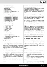
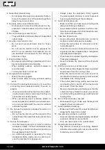
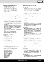
Installing and changing the tool receiver
(Fig. 20 + 21)
m
Attention!
Pull out the mains plug of your machine before chang-
ing the tool receiver (15).
• Select the tool receiver that exactly matches the di-
ameter of your cutter.
• Remove the reducer (14) from the opening (Fig. 20).
• Push the combination spanner SW 18 (16) directly
under the locking nut of the tool receiver (14) and
hold it in place.
• Use the combination screw SW24 (17) to loosen the
locking nut of the tool receiver(14) anti-clockwise.
• Remove the tool receiver (14).
• Now insert the appropriate tool receiver and the ap-
propriate milling tool. The milling tool must be insert-
ed at least 20 mm.
• Tighten the locking nut of the tool receiver (14) with
the Allen wrench SW24 (17).
• Place the reducer (14) for the opening to its original
position.
• Adjust the stop as needed using the scale on the
table.
• Attach the suction system. It is strongly recommend-
ed to connect a suction system to keep the opening
free of chips, to cool the motor and to facilitate work-
piece feeding.
• Re-connect the machine to the mains.
Setting the stop
The use of the stop is mandatory. Each task must be
considered separately. Each time you use the ma-
chine, you must make sure that the protective devic-
es are correctly installed and adjusted. Each time it is
used again, each pressure piece must be readjusted
on the stop.
Make sure that each screw is well tightened before you
start cutting.
Use of the reducers
The reducers (14) must be used to reduce the distance
between the table and the spindle to a minimum. Be-
fore switching on the machine, you must systematical-
ly check that the supplied reducers (14) are correctly
installed.
Check that you have selected the appropriate reducer
(14) for the cutting tool in question and its installation
height in order to reduce the risk of the workpiece tilt-
ing when passing the hole.
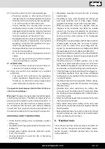
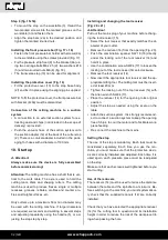
Step 9 (fig. 15+16):
• To mount the stop on the worktable (3), thread the
two marked screws into the marked grooves on the
worktable (3) and fasten them.
• Align the stop bars (2a) in the desired position and
tighten the marked knurled nuts.
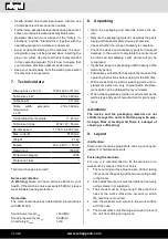
Installing the front pressure bar (Fig. 17 + 18)
• Fasten the front pressure bar holder with screws (9a)
to the worktable using the screws provided (Fig. 17).
• Fix the pressure strip front (9) to the bracket (9a) us-
ing two carriage bolts M6 x 25 (d), two washers Ø 6
(h) and two knurled nuts M6 (b) (fig. 18).
• The transverse stop (10) can be used for alignment.
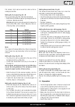
Installing the protective cover (Fig. 19)
• Fit the protective cover (13) to the stop base body
(2f) and fix it in place using the aligning pin supplied.
NOTE: To fit the protective cover, the front pressure bar
with bracket (9+9a) must be dismantled.
Connection of the milling machine to a suction
system
• A connection to an external suction system for ex-
tracting dust and chips (not included in the scope of
delivery) is provided.
• Push the vacuum hose of the suction system onto
the suction adapter (12) at the back of the cutter stop
(2). There is a conical adapter included in the pack-
aging for hoses with a diameter of 100 mm.
10. Start up
m
Attention!
Always make sure the device is fully assembled
before commissioning!
Attention:
The milling machine has a shaft that is ver-
tical to the work table. The axle is used to hold the
cutting tools, discs and shaping cutters. The milling
machine is used to produce friezes, single or multiple
recesses, grooves, rebates, profiles and counter pro
-
files on straight surfaces, etc.
Only cutters up to a maximum 50 mm in diameter may
be used with the milling machine. If larger diameters
are required, we recommend working in several steps
and adjusting repeatedly using the handle (5), or ad-
justing the stop step by step.


