english 15
two above and two below, and if necessary tighten them.
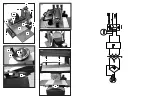
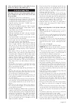
Adjustment of the Cylinder, Fig. 5, 6, 7, 8
•
Warning: In order to avoid serious injury, always unplug
the sanding machine before you begin maintenance or
adjustment work.
1
Check that the positioning screws for the hoisting ten-
sion (Fig. 5) are correct. These screws must be adjusted
to make the height adjustment possible and also to limit
the play of the cylinder. (If the screws are too loose,
then the cylinder has too much play during sanding and
this can make the surface uneven. If the screws are too
tight, then it is difficult to make height adjustments.)
2
In order to position the height adjustment screws,
loosen the safety nuts, which hold the screws in place.
Loosen the screws as necessary a quarter of a turn or
tighten them to achieve the desired level of tightness
and smooth functioning. Tighten the safety nuts again
in order to fix the screws‘ position.
3
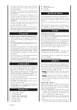
Check the alignment of the sanding cylinder and the
transport table. To do this, first remove the sanding
belt from the cylinder. The goal of this adjustment is
to maintain the same distance between points A and
B, which, in turn, ensures that the cylinder is parallel
to the entry table and thus allows even sanding (see
Fig. 6).
If the distance A is 0.5 mm or less/larger than the same
point at B, proceed as follows:
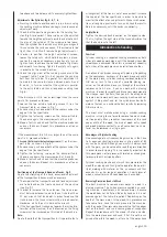
1
Loosen the two outside fastening screws (C) on the
transport table, as shown in Fig. 7.
2
As necessary, push one or both of the spacers under the
edge of the transport table.
3
Tighten the fastening screws on the transport table.
Check once again the measurements at A and B.
4
Make a test run and check that the machine produces
an even thickness. Repeat this procedure as often as
necessary.
If the measurement B is 0.5 mm larger than at the same
point in A, proceed as follows:
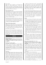
1 Loosen the two outside fastening screws
(C) on the trans-
port table, as shown in Fig. 8.
2
As necessary, push one or both of the spacers under the
edge of the transport table.
3
Tighten the fastening screws on the transport table.
Check, once again, the measurements at A and B.
4
Make a test run and check that the machine produces
an even thickness. Repeat this procedure as often as
necessary.
Positioning of the Transport Band and Tracks
, Fig. 9
Due to the stretching of the band, occasional adjustment
of the transport band tracks may be necessary.
1
The screws for the transport band and track adjustment
are to be found on the front and back of the machine
(see Fig. 9).
2
In order to increase the track tension, the track screw
must be turned clockwise, while the nut is held with an
11 mm wrench (not included). In order to reduce the
track tension, the track screw must be turned counter
clockwise, while the nut is held with a wrench.
3
If the transport band track veers towards the inside (mo-
tor side) of the machine, then the tension on the fixing
screw must be increased on this side of the machine.
Note:
Due to the width of the transport band, it is possible that a
misalignment of the track is not at once evident. Increase
the speed of the transport band in order to be able to
monitor the effect of any adjustments. Make small correc-
tions, of roughly a quarter of a turn, and check the results.
Adjust as necessary, until the bands run correctly.
Helpful Note:
Tighten the desired track direction on the opposite side.
That is, tighten the right side of the track adjustment so
that the band runs to the left.
Introduction to Sanding
Function
Cylinder sanding is a repeated sanding procedure on both
sides of a wooden work piece, until the desired size and/or
smoothness is achieved. When this is carried out correctly,
both sides of the work piece run parallel to each other.
Do not confuse cylinder sanding with planing. Depending
on the coarseness, hardness of the work piece and width
of the work piece, cylinder sanding removes material to
0.8 mm or less. In the case of a portable planing ma-
chine, on the other hand, one run through of the material
removes up to 3.2 mm. If you can work with a planing
machine, in order to smooth and plane your work piece to
the size you want to attain, then you will be able quickly
to learn how to work with your sanding machine and not
against it. Be patient and let the cylinder sander do its
work so that you can achieve the best results by removing
0.8 mm or less.
The most usual mistake when using a cylinder-sanding
machine is trying to use force to remove too much mate-
rial too quickly. Many variables (coarseness of the sand
paper, width of the wood, the kind of wood, entry speed
and wood moisture content) can influence how much ma-
terial can be removed in a single pass.
Advantages of Cylinder Sanding
One advantage of a cylinder-sanding machine is that, due
to its open construction, work pieces up to a width of 81
cm can be handled. Although you must still always sand
with the grain, you do not need to read the grain direction
in order to avoid ripping. This is especially important for
thin work pieces, or for pieces with twisted or mixed grain,
for example with a striped pattern.
Cylinder sanding machines put much less pressure on the
wood than planing and thus give the operator the possibil-
ity of working with material as thin as veneers and thus
expands his or her range of operations. Short pieces of
wood, unusual forms and head wood can be sanded.
Removing Crosswise Bends in Wood
The best machine to remove cross warps in wood is a
planing machine. The limited pressure applied by a sand-
ing machine, nonetheless, can remove warps, because
the wood does not lie flat on the entry band and it is not
pressed against the table. Be patient. Depending on the
depth of the cross warps, in the wood, this procedure can
take some time. Lead the work piece into the machine,
with the peak of the cross warp upwards (so that the edges
rest on the band), and use a coarse grade of sandpaper.
Repeat the procedure until the crown is flat on one side.
Turn the work piece over and sand it flat. Do not be sur-
prised at how thin the wood is, after all of the warps have

