pushed forwards with the push block.
• Chamfering or bevelling: The work piece is
positioned against the jointing fence. Set
the guard rail of the cutterblock cover to the
width of the work piece and place it on the
table. The work piece is pressed against the
fence and the unloading table with the left
hand, fist closed, and pushed forwards with
the closed right hand.
• Warning! Never work with a jointer without
the cutterblock cover.
Electric connection
m
• Check the mains connection cables. Do not
use faulty cables. See Electric connection.
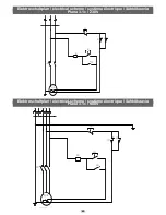
• Observe the rotational direction of the motor
and the tools, see Electric connection planer.
• Installations, repairs and maintenance on the
electric installation may be carried out only
by experts.
• Turn the machine off when resolving issues.
Disconnect the mains plug.
• Turn the motor off when you leave the work
place. Disconnect the mains plug.
• Disconnect the machine from every external
energy supply even for slight changes of
position! Connect the machine to the mains
again before using it!
Connect the machine to the mains with a
CEE-plug, the supply line has to be protected
with 16 A.
On the operating switch, press the green push
button, the cutterblock starts up (fig. 14).
To turn it off, press the red push button, the
cutterblock stops within 10 sec.
Change of rotational direction
When connecting the machine to the mains or
changing its position, the rotational direction
has to be checked. The polarity has to be
swapped, if applicable, using a screw driver
(machine socket fig. 15).
The installed electric motor is connected and
operational. The connection complies with
relevant VDE and DIN stipulations. The mains
connection at the customer’s as well as the
extension lead used have to comply with these
stipulations or the local EVU-stipulations.
Duration of use / duty cycle
The electric motor is for operating type S1 for
continuous operation.
When there is an overload, the motor turns
itself off because a winding thermostat is
integrated in the motor development. After a
cool-down period (timing varies), the motor
can be turned on again.
Hazardous electric connections
Insulation damage often occurs on electric
connections.
Possible causes:
• Pressure marks when connections are gui-
ded through windows and doors
• Kinks due to inappropriate attachment or
guidance of the connection
• Cuts when the connection is run over
• Insulation damage when being pulled out of
the wall socket
• Tears from ageing insulation. Such hazar-
dous electric connections must not be used
and are dangerous to life due to the insulati-
on damage.
Regularly check electric connections for
damage. Make sure the connection is not con-
nected to the mains when checking. Electric
connections must comply with relevant VDE
and DIN stipulations and the local EVE stipula-
tions. Only use connections marked H 07 RN.
Printing the type designation on the connec-
tion is the law.
Extension leads up to 25 m in length must
have a cross section of 1.5 mm2, at more than
25 m length, it has to be at least 2.5 mm2.
The mains connection is protected against
short circuit with a 16 A slow fuse.
Three-phase motor
The power voltage has to be 380÷420 V 50
Hz.
Mains connection and extension leads have to
be 5 core =3 P + N + SL.
Extension leads must have a minimum cross
section of 1.5 mm².
The mains connection is protected against
short circuit at a maximum of 16 A.
When connecting the machine to the mains or
changing its position, the rotational direction
has to be checked. The polarity has to be
swapped, if applicable, using a screw driver
(machine socket fig. 15).
One-phase motor
The power voltage has to be 230 V 50 Hz.
Connections and repairs to the electrical
equipment may be carried out only by a trai-
ned electrician.
If there are any questions, please provide the
following data:
• Motor manufacturer; motor type
• Motor’s type of power
• Data from the machine’s type plate
• Data from the electronic control
When sending back the motor, always send
the entire motor unit with electronic control.
Maintenance
m
WARNING
Before working on the power tool itself (e.g. transport, set-up, re-tooling, cleaning and maintenance), disconnect the mains
plug from the socket!
■
CLEANING
Carry out maintenance, service and repairs
as well as malfunctions only when the motor
is turned off. Turn the machine off via the off-
switch, then disconnect the mains plug!
All protective and safety equipment must be
re-attached immediately after completing
repairs and maintenance.
Always keep the jointer tables and the thick-
nessing table free from resin. The bearings
of the cutterblock are permanently lubricated.
Warmth occurring when the machine is in a
new condition is due to construction and will
disappear with time.
Clean the feed rollers regularly.
After the first 5 operating hours, oil the plain
bearings of the feed rollers, the adjustment
spindle of the thicknessing table, their bea-
rings. Repeat every 20 operating hours with
further use.
Planing knives
The HSS planing knives inserted in the factory
are operational and set up correctly.
Only well-sharpened and correctly set-up
planing knives guarantee safe work.
We recommend: Always keep a second set of
new planing knives ready for replacement.
Replacement planing knives are available
from your stockist.
Inserting planing knives fig. 16
1 Setting screw
2 Pressure screw
3 Planing knives
4 V-ledge
When inserting, be aware that
• there is a risk of injury to fingers and hands.
• the clamping areas in the cutter and the v-
ledges are cleaned.
• the sharpened planing knives are oiled.
• only knives re-sharpened in sets are used.
• inserting the planing knives and v-ledges is
carried out according to the figure.
• the planing knives, knife supports and v-
ledges are flush with the cutter on both sides.
• the clamping screws are tightened (8.9 N/m).
Warning!
The details concerning knife attachment, knife
protrusion, knife width, min. clamping length
and ideal tightening torque of the knife moun-
ting screws have to be complied with exactly.
GB
20
Summary of Contents for plana 3.1c
Page 4: ...1 1 3 4 2 6 5 12 10 8 9 13 7 11 4...
Page 5: ...2 2 5 3 3 1 A B C 3 4 5 2 1 6 2 1 7 5 6 D 8 D 5...
Page 6: ...9 9 1 9 2 10 11 12 12 1 13 12 9 E 8 7 K L M F G 10 11 D 6...
Page 23: ......
Page 25: ......


