background image

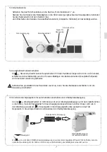
5.3 Initial start-up

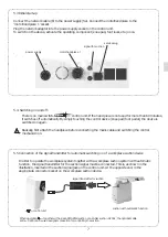
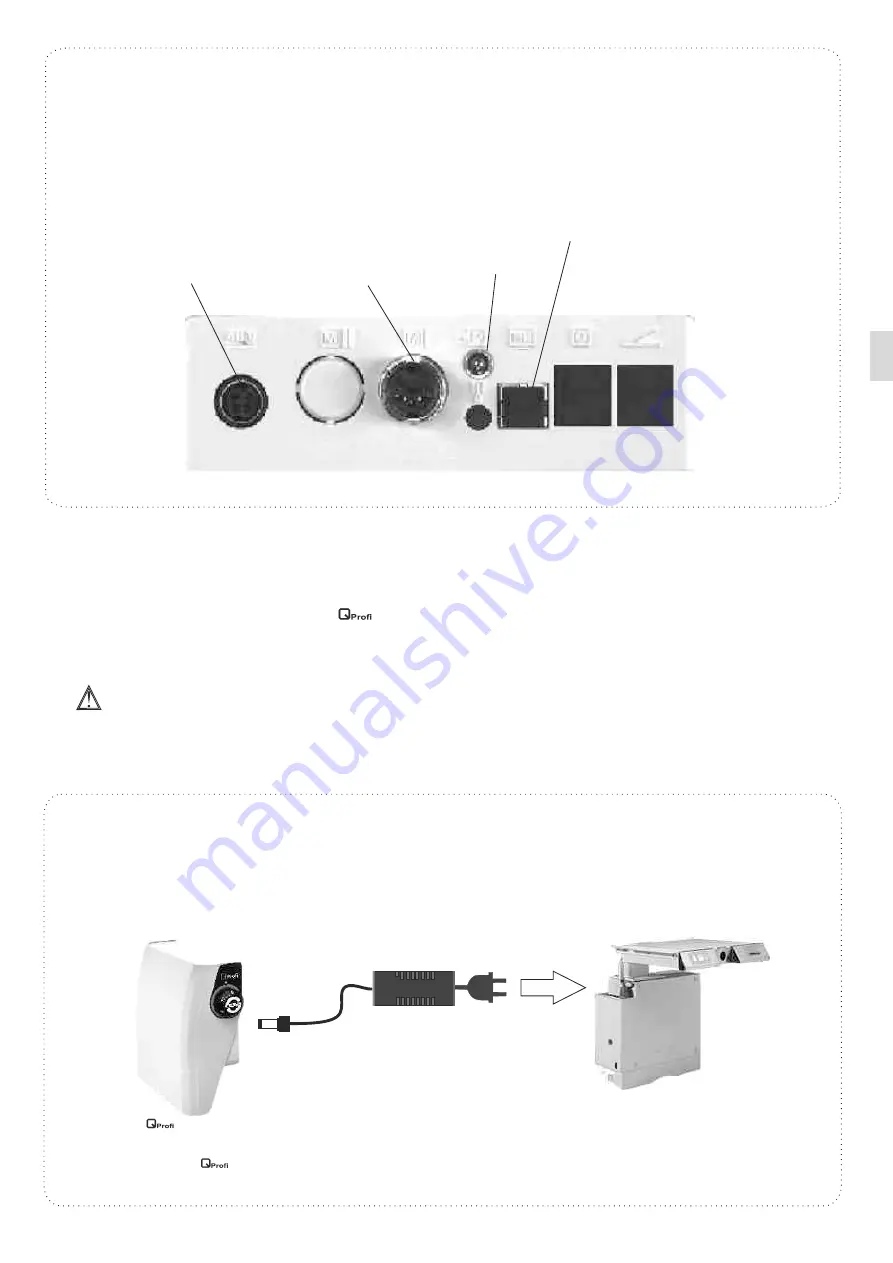
Connect the network cable (6) to the power supply (5a). Connect the motorhandpiece to the 
'motorhandpiece 1 'socket. 
Plug the network adaptor into the power supply socket on the control unit.
To switch on the device, activate the operating component (knee pad, foot lever, etc.) once.


.

motorhandpiece 1 

power supply

serviceplug

signal for suction

There is no main switch for the  

  control unit. If the hand piece is not used for more than 60 minutes, 

it switches off automatically. By simply touching the control device (knee pad /foot pedal), the device is 
switched on again.

Basically, first attach the handpiece before connecting the mains cable and switching the control 
mechanism on.

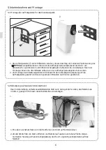
5.5 Connection of the signal transmitter for automatic swichting on of a workplace suction device
      
      In order to operate the workplace system together with a workplace suction system with automatic
      function, the signal transmitter for the suction signal must be connected. This is, as shown in the 
      illustration, inserted in the suction signal jack on the control unit. At the opposite end, in the 
      appropriate connector socket on the workplace suction device.


.

signal transmitter for suction

5.4. Switching on and off:

7

suction with automatic function


 control unit

When operation  

 together with a KaVo SMARTair suction or a Zubler suction AP 501, the optional cable 

art.no.: 9229 can be used as signal connection for controlling the suction.

Summary of Contents for Profi

Page 1: ...Betriebsanleitung D Original E E Operating Instructions Mode d emploi Istruzioni per l uso Instrucciones de uso F I ES ...

Page 2: ... Störungen 10 Technische Daten 11 Konformitätserklärung 3 3 4 5 6 7 8 8 9 10 10 11 Wir freuen uns dass Sie sich für ein technisch hochwertiges Gerät aus dem Hause SCHICK entschieden haben und wünschen Ihnen mit Ihrem neuen Antriebsgerät viel Erfolg und Freude beim Arbeiten Wir haben diese Betriebsanleitung zusammengestellt um Sie mit Ihrem neuen Gerät vertraut zu machen und Ihnen die notwendigen H...

Page 3: ...genommen werden SCHICK übernimmt keine Gewährleistung wenn die Anlage nicht in Übereinstimmung mit der Gebrauchsanweisung gehandhabt wird 2 Einsatz und Gebrauch Die Anlagen sind für den universellen Einsatz im Dentallabor zum Bearbeiten von Kronen Brücken sowie Kunststoff und leichten Modellgussarbeiten konzipiert Das SCHICK Antriebsgerät 1 ermöglicht Ihnen durch einen Drehzahlbereich von 1 000 bi...

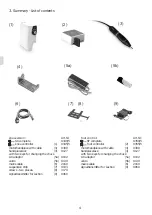
Page 4: ...tzkabel Aufhängeleiste Schrauben 2 Stück Signalgeber für Absaugung Fußversion SF komplett Steuergerät Fußausführung Motorhandstück mit Kabel Handstückablage mit 2 Werkzeugen Netzteil Klett Netzkabel Signalgeber für Absaugung Art Nr 9340 5 9345 5 9300 9127 9102 9130 2160 9103 3170 9060 Art Nr 9350 5 9355 5 9300 9127 9102 9130 2160 9060 1 3 4 5a 5b 6 7 8 9 2 3 4 5a 5b 6 9 2 ...

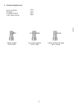
Page 5: ...Zubehör Optionales Spannzange Ø 2 35mm Spannzangenschlüssel Gegenschlüssel Ersatzmotorkabel 6642 4115 6223 9225 Niethammer Art Nr 1850 Doppelniethammer Art Nr 1860 Niethammer mit Meißelaufsatz Art Nr 1850 1 ...

Page 6: ...en werden 2 Zur Montage des Kniesteuergerätes wird dieses mit der rückseitigen Aussparung auf die Aufhängeleiste gesetzt und bis zum spürbaren Einrasten nach hinten geschoben 5 2 Befestigung des Netzteils mittels Klettband Das im Lieferumfang enthaltene selbstklebende Klett kann dazu genutzt werden das Netzteil wie in Abb 2 gezeigt im Fußraum des Arbeitstisches zu befestigen 1 2 1 Eine der zwei Sc...

Page 7: ...ndstück zuerst an bevor Sie das Netzkabel anschließen und die Steuerung einschalten 5 5 Anschluss des Signalgebers für automatisches Zuschalten einer Arbeitsplatzabsaugung Um das Arbeitsplatzsystem in Verbindung mit einer Arbeitsplatzabsaugung mit Automatikfunktion zu betreiben muss der Signalgeber für das Absaugsignal angeschlossen werden Dieser wird wie in der Abbildung gezeigt am Steuergerät in...

Page 8: ...ie Spannzange einsetzen um die maximale Haltekraft zu erzielen 6 Werkzeugwechsel am Motorhandstück 8 Bitte beachten Sie stets die maximal zulässigen Drehzahlen für Ihre Werkzeuge 7 Bedienelemente Über die jeweiligen Bedienelemente siehe Abbildung unten lässt sich das Handstück stufenlos bis zur Höchstdrehzahl regeln Das Kniesteuergerät verfügt zusätzlich über einen Drehknauf über den die maximale ...

Page 9: ...ehen Im Hinblick auf Genauigkeit und Lebensdauer der Spannzange muss auch bei Nichtbetrieb immer ein Werkzeug oder der werkseitig mitgelieferte Schutzstift eingespannt sein Das Handstück niemals mit Druckluft reinigen Die entsprechenden Spannzangenschlüssel finden Sie in der Unterseite der Handstückablage Nach gründlicher Reinigung der Spannzange sollte diese vor dem Wiedereinbau an der Außenseite...

Page 10: ...h eine Störung nicht mittels obiger Beschreibung beheben wenden Sie sich bitte an einen autorisierten Servicepartner oder die Firma Schick direkt Maße Handstück Länge Durchmesser max Gewicht Maße Steuergeräte Knieversion Fußversion Breite Höhe Tiefe Gewicht Nennspannung Nennfrequenz Aufnahmeleistung Drehzahlbereich Fußversion Drehmoment Schutzklasse 158 mm 27 5 mm 240 g 95 mm 203 mm 210 mm 902 g A...

Page 11: ...jede bei uns im Hause durchgeführte Reparatur wird Ihnen wieder eine Garantiezeit von 6 Monaten eingeräumt W Schick Geschäftsführer 11 Konformitätserklärung Wir die SCHICK GmbH Lehenkreuzweg 12 D 88433 Schemmerhofen erklären hiermit dass das Produkt Anlagen bestehend aus Motorhandstück 9300 in Verbindung mit Steuergerät 9345 5 oder 9355 5 Netzteil 9102 und Signalgeber 9060 folgenden einschlägigen ...

Page 12: ...12 D21429 02 17 gz ...

Page 13: ...Original Operating Instructions E E English ...

Page 14: ...ance Removing the chuck 9 Errors 10 Technical data 11 Declaration of conformity 3 3 4 5 6 7 8 8 9 10 10 11 We are pleased that you decided to buy a highly developed piece of equipment from SCHICK and would like to wish you every success when working with your new We wrote these operating instructions to enable you to get accustomed to your new piece of equipment and to provide you with the correct...

Page 15: ...nd other technical procedures must only be carried out by suitable qualified personnel authorized by SCHICK SCHICK do not guarantee the unit should it not have been used in accordance with the operating instructions 2 Range of applications The unit is designed for universal use in dental laboratories when trimming crowns and bridges respectively acrylic and light chrome cobalt dentures With its sp...

Page 16: ...screws two pieces signaltransmitter for suction foot control SF complete foot controller motorhandpiece with cable handpiecerack with two keys for changing the chuck AC adaptor velcro mains cable signaltransmitter for suction Art Nr 9340 5 9345 5 9300 9127 9102 9130 2160 9103 3170 9060 Art Nr 9350 5 9355 5 9300 9127 9102 9130 2160 9060 1 3 4 5a 5b 6 7 8 9 2 3 4 5a 5b 6 9 1 3 4 5a 5b 6 7 8 9 2 ...

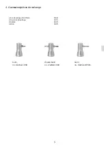
Page 17: ...cessories optionals chuck Ø 2 35mm chuck key counterstay wrench motor cable complete 6642 4115 6223 9225 riveting hammer Art no 1850 twin riveting hammer Art no 1860 riveting hammer with chisel Art no 1850 1 ...

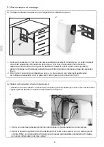
Page 18: ...er installation the template can simply be detached from the bracket 2 For installation of the knee control unit the cavity at the rear of the unit is placed on the bracket and pushed back until it clicks into place fig 2 5 2 Fixing the power supply with the velcro The delivered velcro can be used to attach the power supply under the workbench fig 2 1 2 1 Remove one of the protective foils of the ...

Page 19: ...dpiece before connecting the mains cable and switching the control mechanism on 5 5 Connection of the signal transmitter for automatic swichting on of a workplace suction device In order to operate the workplace system together with a workplace suction system with automatic function the signal transmitter for the suction signal must be connected This is as shown in the illustration inserted in the...

Page 20: ...s possible into the chuck in order to achieve maximum holding power 6 Tool change on motorhandpiece 8 Please always observe the maximum permitted speed for your tools 7 Operation There is continuously variable speed control of the handpiece up to the maximum preset motor speed using the respective control unit see figure below The knee controller is equipped with an additional potentiometer for se...

Page 21: ... and durability of the chuck a tool or the factory supplied protective pin must always be fixed even when not in use Never clean the handpiece with compressed air The required chuck keys are located in the underside of the handpiece holder After thoroughly cleaning the chuck before replacing it should be slightly greased on the outer surface art no 51 1 grease Only fasten the chuck lightly when re...

Page 22: ...osition the unit can continue operation If an error cannot be removed following the above description please contact an authorised service partner or Schick directly dimensions handpiece length diameter max weight dimensions control unit knee version foot version width height depth weight operating voltage Frequency output speed range foot control torque protection class 158 mm 27 5 mm 240 g 95 mm...

Page 23: ...f person in charge Schemmerhofen February 2016 Wolfgang Schick Lehenkreuzweg 12 88433 Schemmerhofen manufacturer This unit complies with the current VDE German association of electrical technicians regulations concerning safety and suppression These operating instructions should be readily accessible and are best kept close to the unit itself We would like to take this opportunity to advise you th...

Page 24: ...12 D21429 02 17 gz ...

Page 25: ...Mode d emploi F Originale Français ...

Page 26: ...ince de serrage 9 Possibles messages d erreur 10 Données techniques 11 Déclaration de Conformité Nous nous réjouissons de votre décision d utiliser un appareil de haute technicité de la société SCHICK et nous vous souhaitons avec votre nouvelle pièce à main beaucoup de satisfications dans votre travail Nous avons rédigé ce mode d emploi pour vous familiariser avec votre nouvel appareil et pour vou...

Page 27: ...s ne peuvent être faites que par les personne qualifiées et autorisées par SCHICK SCHICK ne prend en charge aucune prestation de garantie dans le cas où le moteur n aurait pas été utilisé selon les prescriptions d emploi 2 Domaine d application et utilisation Les moteurs sont conçus pour des travaux de façonnage de couronnes de bridges et pour des travaux intensifs en résine et prothèse partielles...

Page 28: ...mande actionné avec le genou pièce à main et cable support pour pièce à main avec deux clés pour changer la pince alimentation électrique velcro câble d alimentation liteau de suspension vis 2 pièces transmetteur de signaux pour aspiration SF complet appareil de commande actionné avec le pied pièce à main et cable support pour pièce à main avec deux clés pour changer la pince alimentation électriq...

Page 29: ...pince de serrage Ø 2 35mm clé p pince de serrage clé plate cordon 6642 4115 6223 9225 4 Accessoires pièces de rechange burin no d article 1850 double burin no d article 1860 burin no d article 1850 1 5 ...

Page 30: ...l de commande au genou on place celui ci sur l évidement pastille situé sur le liteau de suspension et on le glisse vers l arrière jusqu à enclenchement fig 2 5 2 Fixation du bloc secteur à l aide de bande velcro La bande velcro autocollante contenue dans la livraison peut être utilisée pour fixer le bloc secteur dans l espace pied de la table de travail comme illustré sur la figure 2 1 2 1 Retire...

Page 31: ...n Comme le montre l illustration le transmetteur de signal est branché sur le bôitier de commande sur la connexion spécifique De l autre côté le transmetteur est installé sur la prise de courant de l aspirateur à destination du micro moteur transmetteur de signaux pour aspiration Aspiration du poste de travail avec fonction automatique appareil de commande 5 4 Activer et éteindre La commande ne po...

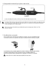
Page 32: ...tante maximale 6 Changement d instrument sur la pièce à main moteur 8 ouvert fermé tenir ici 7 Des éléments de commande Veuillez observer les vitesses maximales admissibles des instruments Grâce aux éléments de commande voir l illustration ci dessous vous avez la possibilité de régler la vitesse de la pièce à main progressivement jusqu à la vitesse de rotation maximale pré ajustée La commande au g...

Page 33: ...pièce à main Pour conserver la précision et préserver la durée de vie de la pince de serrage elle doit toujours être munie d un instrument ou de la pointe fournie à la livraison et ce même au repos Ne nettoyer jamais la pièce à main avec de l air comprimé Vous trouverez la clé pour pince de serrage et les clés à fourche sous le support de la pièce à main Après un nettoyage minutieux de la pince de...

Page 34: ...e agréé du service après vente ou l entreprise Schick directement 10 Données techniques dimensions piece à main longuer diameter max poids dimensions appareils de commande modèle au genou modèle au pied largeur hauteur profondeur poids tensions nominale fréquence nominale puissance intervalle de vitesse modèle au pied de rotation max classe de protection La valeur totale d osciallation dans l oper...

Page 35: ... garanti des réparations parfaites avec des pièces de rechange d origine Fabricante Sous réserve de modifications techniques W Schick manager 11 Declaration of Conformity We the SCHICK GmbH Lehenkreuzweg 12 D 88433 Schemmerhofen declare herewith that the products consisting of handpiece 9300 in combination with control unit 9345 5 or 9355 5 power supply 9102 and pulse emitter for suction 9060 are ...

Page 36: ...12 D21429 02 17 gz ...

Page 37: ...Istruzioni per l uso Originale Italiano I I ...

Page 38: ...o della pinza portante 9 Disturbi 10 Dati tecnici 11 Cichiarazione di conformitá 3 3 4 5 6 7 8 8 9 10 10 11 Complimenti per la Sua scelta di un apparecchio di elevate qualità tecniche della SCHICK e le auguriamo successo e soddisfazione nel suo lavoro con il dispositivo di comando Queste istruzioni per l uso sono state concepite per facilitarle la conoscenza dell apparecchio e per darle le necessa...

Page 39: ... Grado di insudiciamento 2 1 Informazioni di sicurezza 1 1 Controllare se la tensione di rete corrisponde a quella indicata sulla targhetta dell apparecchio 1 2 Gil apparecchi non devono essere usati nei casi di ambienti a pericolo di esplosione sui pazienti lavorazione di materiali umidi 1 3 Durante la lavorazione osservare le regole di prevenzione degli infortuni uso continuo di occhiali di prot...

Page 40: ...i 2 pezzi segnalatore per il segnale di aspirazione modello con comando a pedale SF del tutto modello con comando a pedale Manipolo a motore con cavo Appagio per manipolo con 2 chiavi per pinza alimentatore velcro cavo collegamento rete segnalatore per il segnale di aspirazione cod art 9340 5 9345 5 9300 9127 9102 9130 2160 9103 3170 9060 1 3 4 5a 5b 6 7 8 9 cod art 9350 5 9355 5 9300 9127 9102 91...

Page 41: ...6642 4115 6223 9225 Martello per rivetare cod art 1850 Martello per rivetare cod art 1860 Martelo per rivetare cod art 1850 1 pinza portante Ø 2 35mm pinza di serragio chiave a forchetta cavo di ricambo per il motore ...

Page 42: ...lacca di sospensione 2 Il dispositivo di comando a ginocchio viene montato accostando la tacca sul lato posteriore alla placca di sospensione e spingendo contro la placca fino a udire lo scatto di innesto Fig 2 5 2 Fissaggio dell alimentatore con nastro a velcro Il velcro autoadesivo incluso nella fornitura viene utilizzato per fissare l alimentatore sotto il piano di lavoro come illustrato in Fig...

Page 43: ...atore per il segnale di aspirazione Questo viene inserito da un lato nella presa per il segnale di spirazione sull unità di comando come mostrato in figura e dall altro nell apposita presa di connessione dell aspiratore per postazione di lavoro segnalatore per il segnale di aspirazione 5 4 Accendere e spegnere 7 Aspiratore per postazione di lavoro con funzione di accensione automatica Unita di com...

Page 44: ... rotazioni sul valore predefinito aperto chiuso tenere fermo qui Ruotando il rivestimento dell impugnatura del manipolo è possibile aprire o chiudere la pinza di serraggio 6 Sostituzione dell utensile sul manipolo elettrico Sostituire l utensile esclusivamente a motore spento Per una maggiore precisione e durata della pinza di serraggio anche quando il manipolo non è in funzione è opportuno lascia...

Page 45: ... quando il manipolo non è in funzione è opportuno lasciare inserito un utensile o l apposito spinotto di protezione incluso nella fornitura Il manipolo non deve in nessun caso essere pulito con aria compressa La chiave per la pinza di serraggio e la chiave a forchetta si trovano nella parte inferiore del supporto del manipolo Dopo aver eseguito un accurata pulizia è consigliabile applicare un sott...

Page 46: ...za autorizzati o direttamente l azienda Schick 10 Dati tecnici manipolo lunghezza diametro max peso strumenti di comando larghezza altezza profondita peso Tensione d escercizio frequenca nominale potenza velocità di rotazione modello con comando a pedale torque classe di protezione Il valore totale di vibrazione durante l esercizio è inferiore a 2 5m s 158 mm 27 5 mm 240 g 95 mm 203 mm 210 mm 902 ...

Page 47: ...ali Ci riserviamo modifiche tecniche W Schick manager 11 Declaration of Conformity We the SCHICK GmbH Lehenkreuzweg 12 D 88433 Schemmerhofen declare herewith that the products consisting of handpiece 9300 in combination with control unit 9345 5 or 9355 5 power supply 9102 and pulse emitter for suction 9060 are in conformity with the following provisions of Directive 2006 42 EG machinery directive ...

Page 48: ...12 D21429 02 17 gz ...

Page 49: ...Instrucciones de uso Original Español ES ...

Page 50: ...arato y proporcionarle los consejos necesarios para su manejo y mantenimiento Contenido pagina 1 Informaciones de seguridad Atención 2 Indicación y uso 3 Relación de los modelos 4 Relación de los modelos y sus componentes 5 Puesta en servicio Encender y apagar la máquina 6 Cambio de herramientas en el micromotor 7 Funcionamiento 8 Limpieza y mantenimiento 9 Fallos 10 Datos técnicos 11 Declaración ...

Page 51: ...ersonal técnico autorizado por SCHICK SCHICK no acepta trabajos en garantía cuando el equipo no ha sido manipulado de acuerdo con las instrucciones de uso 2 Indicación y uso Los aparatos están previstos para el uso universal en el laboratorio dental para el trabajo de coronas y puentes así como para trabajos de moldeo y plásticos El motor SCHICK le permite con su gama de revoluciones de 1 000 hast...

Page 52: ... caja de mando versión rodilla pieza de mano con cable soporte pieza de mano con 2 llaves para pinza de sujeción fuente de alimentación velcro cable de red guia para colgar tornillos 2 piezas señal para extracción SF completo caja de mando versión de pie pieza de mano con cable soporte pieza de mano con 2 llaves para pinza de sujeción fuente de alimentación velcro cable de red señal para extracció...

Page 53: ...s componentes Relación de los modelos y s pinza Ø 2 35mm llave contra llave cable 6642 4115 6223 9225 martillo solo No de ref 1850 martillo doble No de ref 1850 2 martillo con el cincel No de ref 1850 1 5 ...

Page 54: ... colocará éste con sus partes sobresalientes dentro de los orificios de la placa colgante luego se empujará hacia atras hasta que las partes sobresalientes queden fijadas y ajustadas en los orificios Como se observa en la Fig 2 1 2 1 2 6 5 2 Montaje de la fuente de alimentación por medio de la cinta de velcro Con al adhesivo de velcro incluido se puede ajustar la fuente de alimentación a la zona i...

Page 55: ...l elemento de control placa de rodilla pedal el aparato vuelve a ponerse en marcha 5 4 Conexión del interruptor automático para la conexión automática de la sonda de extracción Para operar el sistema de extracción de trabajo automáticamente se tiene que conectar primeramente la señal de extracción tal como lo muestra en la figura se insertará en el dispositivo de mando ECU previsto para la extracc...

Page 56: ... la pinza para obtener la máxima sujectión 6 Cambio de herramientas en la pieza de mano 8 Preste atención a la velocidad máxima permitida para sus herramientas 7 Funcionamiento Mediante los respectivos controles ver imagen abajo se puede ajustar la pieza de mano continuamente hasta el número máx de revoluciones El controlador de rodilla dispone además de un mando giratorio mediante el que se puede...

Page 57: ...e la pinza aun cuando no esté en uso siempre ponga una herramienta o el lápiz de protección que la fábrica ha suministrado No limpie las piezas de mano con aire comprimido Las llaves se encuentran al parte inferior del soporte de la pieza de mano Después de una limpieza de la pinza y antes de volverla a instalar engrásela ligeramente por fuera con grasa no 51 1 Aprete un poco la pinza a su posició...

Page 58: ...se puede solucionar el fallo con el método descrito arriba diríjase a un servicio técnico autorizado o directamente a la empresa Schick Pieza de mano Longitud Diámetro máximo Peso Módulos de mando Control de rodilla Control de pie Ancho Alto Fondo Peso Tensión nominal Frecuencia nominal Potencia absorbida Número de revoluciones control de pie Torque Clase de protección 158 mm 27 5 mm 240 g 95 mm 2...

Page 59: ...ambios técnicos reservados fabricante W Schick manager 11 Declaration of Conformity We the SCHICK GmbH Lehenkreuzweg 12 D 88433 Schemmerhofen declare herewith that the products consisting of handpiece 9300 in combination with control unit 9345 5 or 9355 5 power supply 9102 and pulse emitter for suction 9060 are in conformity with the following provisions of Directive 2006 42 EG machinery directive...

Page 60: ...12 D21429 02 17 gz ...
Reviews: