background image

About this operating manual 1 

Issue Q3 

1.4


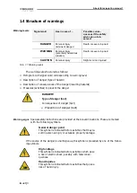
Structure of warnings 

Signal word 

Use in case of ... 

Possible conse-

quences if the safety 

advice is not ob-

served: 

DANGER 

Personal injury 
(imminent danger) 

Death or severe injuries! 

WARNING 

Personal injury 
(potentially hazardous 
situation) 

Death or severe injuries! 

CAUTION 

Personal injury 

Slight or minor injuries! 

Tab. 1.1 Warning levels 

The warnings are structured as follows: 


Pictogram with signal word corresponding to warning level 


Description of danger (type of hazard) 


Description of consequences of the danger (resulting hazards) 


Measures (activities) to prevent the danger 


DANGER! 
Type of danger (text) 

Consequences of danger (text) 


Prevention of danger (text) 


Special safety instructions are provided at the relevant locations. These are marked 

with the following symbols. 


General danger point 

This symbol is indicated before activities that may re-

sult in personal injury or extensive property damage. 

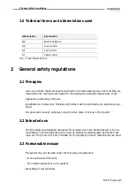
If the source of the danger is unambiguous, this symbol is preceded by one of the follow-

ing symbols. 


High voltage 

This symbol is indicated before activities which pose 

a risk of electric shock, possibly with fatal conse-

quences. 


Hand injuries 

This symbol is indicated before activities that pose a 

risk of hand injury. 

Warning levels 

Warning signs 

Summary of Contents for 10765

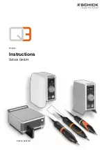
Page 1: ...Edition 2021 10 Instructions Schick GmbH Original ...

Page 2: ...r to acquaint you with your new device and pro vide the necessary information for operation and maintenance Project data Trade name Schick Q3 Q3 Basic Q3 Profi Q3 Premium Serial number Axxx xxx Type Q3 engineering machine Manufacturer Schick GmbH Lehenkreuzweg 12 D 88433 Schemmerhofen Tel 49 7356 95000 Fax 49 7356 950095 info schick dental de www schick dental de www schick industrie de Revision d...

Page 3: ...8 2 3 Foreseeable misuse 8 2 4 Selection and qualification of the personnel 9 2 5 Workstations for operating personnel 9 2 6 Safety equipment 9 Fire protection 9 2 7 Safety signs 10 Explanation 10 2 8 Safety measures 10 Personal protective equipment 10 2 9 Safety regulations 10 General information 10 During transport 10 During installation 10 During operation 11 Care and control work 11 Maintenanc...

Page 4: ...5 6 1 Installation 15 Required tools 15 Safety precautions before installation 15 Installation 15 Installing the control unit on the mounting bracket 16 6 2 Commissioning 17 Establish power supply 17 7 Control satellite optional not included in delivery 18 8 Power stick optional not included 18 9 Functions and operation 19 9 1 Control units Q3 on off 19 9 2 Operating concept and OLED display 19 9 ...

Page 5: ... information 24 11 2 Care and inspection plan 24 11 3 Performing care and control work 24 Removal and cleaning of the collet on the Q Basic handpiece 24 Removal and cleaning of the collet on the Q Profi handpiece 25 Removal and cleaning of the collet chuck on the Q Premium handpiece 25 Disassembly of the motor cable on the Q Premium handpiece 26 12 Technical specifications 27 13 Annex 28 13 1 Serv...

Page 6: ...ce life of the product These instructions must be read and used by everyone who is entrusted with working with Q3 In addition to this operating manual the regulations on accident prevention and environ mental protection applicable at the place of installation must also be observed 1 2 Related documentation The latest version of this manual as well as up to date product information is always avail ...

Page 7: ... the danger resulting hazards Measures activities to prevent the danger DANGER Type of danger text Consequences of danger text Prevention of danger text Special safety instructions are provided at the relevant locations These are marked with the following symbols General danger point This symbol is indicated before activities that may re sult in personal injury or extensive property damage If the ...

Page 8: ...mmerce Qualifications of personnel Trainees and interns must be instructed by an experienced op erator It is operated manually optionally using the knee plate foot lever or foot pedal 2 2 Intended use The Q3 systems are designed exclusively for universal use in the dental laboratory for dry processing of solid workpieces such as crowns bridges as well as plastic and model cast ing work Only tools ...

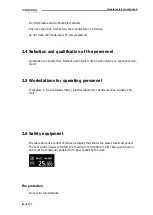
Page 9: ...nterns must be instructed by an experienced op erator 2 5 Workstations for operating personnel Workplace in the dental laboratory practice laboratory dental practice industry and craft 2 6 Safety equipment The table and knee control units have a display that shows the preset maximum speed The foot control device is limited to a maximum of 30 000 rpm after being switched on and must be consciously ...

Page 10: ...ir open Always use suction Personal protective equipment Protective goggles Extraction at the workplace 2 9 Safety regulations General information Caution Risk of injury from sharp and or rotating tools Wear safety goggles During transport Transport or shipping only in the original packaging or a suitable shipping box During installation Access to the power supply must not be made more difficult b...

Page 11: ...nd interns must be instructed by an experienced operator Maintenance and repair work Only by the manufacturer Only trained personnel with specialist knowledge of the respective device class may implement configuration Structural modifications Structural changes to the product are not permitted 2 10 Upgrading and conversion The control satellite of the QUBE and QUBE II series can be connected to th...

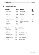
Page 12: ... Handpiece with cable 10720 9300 9400 3 Handpiece holder with two tools 9127 Power line 9415 Power line 9415 Handpiece holder with two tools 9127 Hanging bar 9103 Two screws 3170 Table version Item No Optional item no Q3 Premium ST 10793 Q3 Profi ST 10783 Q3 Basic ST 10773 Foot pedal switch on off Handpiece with cable 10720 9300 9400 3 9440 foot control Handpiece holder with two tools 9127 Control...

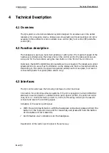
Page 13: ...re shown as well as the limitation via the display and the touch sensitive buttons Depending on the version the speed is regulated variably via the knee plate foot lever or connected dynamic foot pedal table version only 4 3 Interfaces The Q3 control units have the following interfaces to other machines Connection for controlling extraction systems If the Q3 is operated on a KaVo SMARTair stand al...

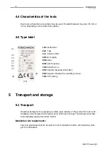
Page 14: ...he goods this must be im mediately communicated to the carrier and confirmed in writing The damage must then be immediately reported to Schick GmbH Installation site requirements Very cold appliances must be brought to room temperature before commissioning Dan ger of condensation 1 2 3 5 6 7 8 4 9 10 1stManufacturer 2nd Type 3rd Serial number 4thPower supply 5thOutput 6thMains frequency 7thOrder a...

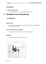
Page 15: ...stallation and commissioning 6 1 Installation Required tools For knee desktop variant Phillips head screwdriver possibly a drill cordless screwdriver for fastening the hanging rack Safety precautions before installation Unplug the power cord before working on the electrical equipment Installation Assembly of the suspension bar for the knee device ...

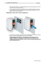
Page 16: ...bly simply break off the spacers on the mounting bracket Installing the control unit on the mounting bracket To mount the knee control device place the recessed backside on the mounting bracket and push it backwards until you can feel it latch in The Q3 hanging rail is identical to the hanging rail of the Q Basic Q Profi QUBE and QUBE II Accordingly the Q3 knee device can be attached to the workpl...

Page 17: ...ree socket control satellite or foot pe dal Optional Connect a suction point signal cable or signal transmitter to the Sig nal cable for suction socket for use of the interface see page 13 4 3 Insert the AC adapter plug into the power socket of the control unit Only when the handpiece and control satellite optional have been correctly connected to the control unit plug the power cord into the sock...

Page 18: ...tellite the operating instructions supplied with the control satellite must be observed 8 Power stick optional not included Q3 has the option of plugging a Power stick into the connection socket of the foot pedal or control satellite which increases the performance of the Q3 Basic and Q3 Profi by 2 Ncm as well as increasing the maximum speed by 10 000 rpm The power stick cannot be used with the Q3...

Page 19: ... using the main switch when the handpiece is stopped 9 2 Operating concept and OLED display The OLED display of the Q3 control device knee and table version only provides infor mation about all operating states of the device after switching on In particular the following parameters are displayed Ready for operation The display shows the preselected maximum speed the maxi mum possible speed for the...

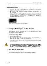
Page 20: ...ase via button up to the maximum speed of the corresponding device variant Version table top device Variable speed control using the optional dynamic foot pedal item number 9440 up to the maximum speed set using the rotary knob Static handpiece start via the button to the speed set via the rotary knob Static handpiece start via the optional foot pedal switch item number 6370 2 to the speed set via...

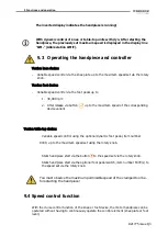
Page 21: ... Changing the handpiece rotation direction The Q3 handpiece can be switched from clockwise to counterclockwise rotation The de fault direction of rotation is right hand Changing the direction of rotation Briefly press the button The symbol or on the display shows the selected direction of rotation or the LED next to the symbol on the foot device lights up The change in the direction of rotation is...

Page 22: ...e display as soon as the knee plate or foot pedal is released or the fault is eliminated This means there are no waiting times for re starting If a fault can not be solved with the above procedure please contact an authorized service partner or Schick directly 10 2 Fault and error messages The Q3 control units have intelligent control electronics that recognize possible malfunc tions and can show ...

Page 23: ... checked when Control is on Check whether the handpiece is connected correctly 02 Error in the handpiece ca ble 1 A motor phase not contacted Is always checked when the con trol is on Replace the motor cable 03 Motor blocked when start ing 2 Collet open or handpiece blocked due to bearing damage Check whether the tool can ro tate freely 04 Motor blocked while run ning 2 Motor blocked for more than...

Page 24: ...ction plan Care and control plan for the handpiece Interval Care and inspection tasks Remarks Weekly Dismantle the tip and remove dirt Do not use compressed air Once a month Dismantle the collet chuck clean and lubricate Lubricate with Article no 51 1 11 3 Performing care and control work Removal and cleaning of the collet on the Q Basic handpiece 1 Remove the tool unscrew the tip 2 Unscrew and re...

Page 25: ...huck key Article no 4115 into the open collet chuck counterhold the chuck on the opposite side on the shaft with the open ended wrench item no 6223 and jerk the collet chuck out with a sudden movement or by knocking on the collet key if necessary 4 Remove the collet chuck from the shaft Removal and cleaning of the collet chuck on the Q Premium handpiece 1 Remove the tool and unscrew the tip 2 Inse...

Page 26: ...ns itself In order to preserve the collet chuck s accuracy and service life a tool or the protective pin provided from factory must always be clamped even when the unit is not being operated Never clean the handpiece with compressed air The corresponding collet chuck tools can be found on the underside of the handpiece rest Disassembly of the motor cable on the Q Premium handpiece 1 Unscrew the ti...

Page 27: ...sed system without cooling Drive system Brushless DC motor Brushless DC motor Brushless DC motor Concentricity 0 02 mm 0 02 mm 0 02 mm Collets Ø 2 35 and 3 0 mm optional Ø 2 35 and 3 0 mm optional Ø 2 35 and 3 0 mm op tional Tool change Quick release Quick release Quick release Control devices Dimensions Knee device Foot device Table top unit broad 128 mm 175 mm 106 mm height 208 mm 95 mm 200 mm d...

Page 28: ...500 95 Email info schick dental de Internet www schick dental de www schick industrie de Schick GmbH reserves the right to change this documentation and the descrip tions dimensions and technical data contained herein without prior notice Schick GmbH assumes no responsibility for possible errors in this documentation In no event shall Schick GmbH be liable for damages or consequential damages resu...

Page 29: ...resentative In the community Schemmerhofen October 2021 W Schick Managing Director Technical changes reserved The device complies with the device safety and the Radio protection in accordance with the applicable regulations according to VDE These instructions for use are always available ideally in to be kept close to the device At this point we would also like to point out that a corresponding on...

Reviews: