background image


List of Figures 

Figure 1. CDR Wireless System.......................................................................................................4 
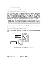
Figure 2. Wireless Sensor with Battery Pack Removed...................................................................5 
Figure 3. Antenna / Receiver............................................................................................................6 
Figure 4. USB Interface....................................................................................................................7 
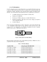
Figure 5. USB Connector and Cable Marking .................................................................................8 
Figure 6. Wireless Monitor...............................................................................................................9 
Figure 7. Wireless Tools ..................................................................................................................9 
Figure 8. USB Interface with Protective Panel Attached ...............

Error! Bookmark not defined.


Figure 9. Antenna / Receiver with Protective Panel Attached .......

Error! Bookmark not defined.


Figure 10. Antenna / Receiver Base ...............................................

Error! Bookmark not defined.


Figure 11. USB Interface Base.......................................................

Error! Bookmark not defined.


Figure 12. Wireless Sensor Controls and Indicators ......................

Error! Bookmark not defined.


Figure 13. Antenna / Receiver Connections and Indicators ...........

Error! Bookmark not defined.


Figure 14. USB Interface Connections...........................................

Error! Bookmark not defined.


Figure 15. USB Interface Indicators...............................................

Error! Bookmark not defined.


Figure 16. Wireless Tools Selection Screen...................................

Error! Bookmark not defined.


List of Tables 

Table 1. USB Cable Markings..........................................................................................................8 
Table 2. Placing the Sensor in the Sensor Cradle...........................

Error! Bookmark not defined.


Table 3. Securing the Battery Pack to the Sensor...........................

Error! Bookmark not defined.


Table 4. Wireless Sensor Dual LED Indications............................

Error! Bookmark not defined.


Table 5. USB Interface LED Indications .......................................

Error! Bookmark not defined.


Table 6. Wireless Sensor System Summary...................................

Error! Bookmark not defined.


Table 7. Wireless Sensor System Specifications............................

Error! Bookmark not defined.


ii


B1051301 Rev. - (DRAFT) 

CDR Wireless User Guide 


Summary of Contents for CDR Wireless

Page 1: ...CDR Wireless User Guide Schick Technologies Inc 30 00 47th Avenue Long Island City NY 11101 718 937 5765 718 937 5962 fax PART NUMBER B1051301 REV DRAFT ...

Page 2: ... Numbers 5 912 942 and 6 134 298 Additional patents are pending Trademark designations used by other manufacturers and sellers may appear in this document also Where Schick Technologies Inc was aware of a trademark claim that information has been printed in caps or initial caps February 11 2003 Printed in the United States of America This document was originally prepared in English ...

Page 3: ...Antenna Receiver Error Bookmark not defined 4 3 USB Interface Error Bookmark not defined 5 Using Your Wireless Sensor Error Bookmark not defined 5 1 Sensor Sheaths Error Bookmark not defined 5 2 Sensor Holders Error Bookmark not defined 5 3 Taking X rays Error Bookmark not defined 6 Using the Wireless Tools Utility Error Bookmark not defined 6 1 Introduction Error Bookmark not defined 6 2 Sensor U...

Page 4: ... defined Figure 13 Antenna Receiver Connections and Indicators Error Bookmark not defined Figure 14 USB Interface Connections Error Bookmark not defined Figure 15 USB Interface Indicators Error Bookmark not defined Figure 16 Wireless Tools Selection Screen Error Bookmark not defined List of Tables Table 1 USB Cable Markings 8 Table 2 Placing the Sensor in the Sensor Cradle Error Bookmark not defin...

Page 5: ...s holders and tabs Observe Handling Storage and Disposal Guidelines for Batteries Your CDR Wireless Sensor system is equipped with disposable batteries that have been packaged and protected at the factory Be sure to read the special instructions relating to battery usage and follow all of the guidelines for storage and disposal Radio Frequency RF Interference Considerations Your CDR Wireless Senso...

Page 6: ...ple of this type of mark The remaining symbols provide either technical or directive information as described below Symbol Description Indicates that CDR Wireless is Class II equipment Indicates that CDR Wireless is Type BF equipment Indicates an attention to users to consult accompanying documents the CDR Wireless System User Guide for more information on CDR hardware iv B1051301 Rev DRAFT CDR Wi...

Page 7: ...r Label Description Regulatory Markings and Manufacturer Label located on back of Sensor Battery Package Label Refer to the following figure for labels and markings found on CDR Wireless Sensor Battery Packages Label Description Regulatory Markings and Manufacturer Label CDR Wireless User Guide B1051301 Rev DRAFT v ...

Page 8: ...on Regulatory Markings and Manufacturer Label located on bottom USB Interface Module Label Antenna Receiver Picture of Label Refer to the following figure for labels and markings found on the USB Interface Module Label Description Regulatory Markings and Manufacturer Label located on bottom vi B1051301 Rev DRAFT CDR Wireless User Guide ...
Page 9: ...tive during image transmission other devices that use radio frequency or microwave technology wireless Local Area Networks wireless telecommunication devices microwave ovens may interfere with the optimal performance of your CDR Wireless System For best results turn off other wireless or microwave devices when using your Wireless Sensor 2 Correct placement of the Antenna Receiver with respect to t...

Page 10: ...ages to be displayed on a computer monitor or other display system The unit is powered from the computer s USB port Software used with the CDR Wireless system performs the following actions Wireless Sensor Driver supplied with your system acquires images captured by the Wireless Sensor It also optimizes image quality for display on a computer monitor Wireless Tools Wireless Monitor and Diagnostic ...

Page 11: ...ng current suitable for wireless transmission RJ Registered Jack RJ 45 is the connector type at each end of the Category 5 cable used in the CDR Wireless system to convey data between the Antenna Receiver and USB units when they are not connected directly docked with each other USB Universal Serial Bus Plug and play interface between host computer and connected USB compatible devices CDR Wireless ...

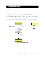
Page 12: ...ram shows the functional relationships between modules and devices within the CDR Wireless system The Antenna Receiver unit can be located remotely from the USB Interface unit via Category 5 cable RJ 45 connectors however in the following illustration they are shown in their default docked configuration Wireless Sensor 2 4 GHz RF Link wireless Base Station Antenna Receiver USB Interface USB Link w...

Page 13: ... in the Wireless Monitor dialog box Figure 6 where RF channel signal strength and Sensor information can be found PLEASE NOTE When detached from the Sensor place the battery pack on its back with the terminals facing upwards Ensure that no conductive object contacts the battery terminalstoeliminateaccidentaldischarge The Sensor ON OFF switch is part of the battery package Turn the Sensor on and of...

Page 14: ... back and rotated from left to right to achieve optimum reception The Antenna Receiver and USB Interface are shipped connected directly to each other docked Two screws are used to secure the units Remote mounting of the Antenna Receiver from the USB Interface is optional and may be prompted by a number of factors including physical layout of the office and or RF reception The base of the Antenna c...

Page 15: ...closed the compartment lid serves to protect the Sensor and battery pack when not in use Dual LEDs are located on the exterior of the USB Interface and supply power and status information about the unit and the Wireless Sensor currently in use LED indications have several states On Off Blinking to reflect various states of operation For more information about the USB Interface LEDs and their indic...

Page 16: ...ecting the USB Interface to the PC workstation verify that the USB cable has a 2c designation marked along the cable typically at either end and close to the connector The 2c designation is the USB spec designation for power connectors inside the cable and is a requirement for this system Figure 5 USB Connector and Cable Marking Different lengths of USB cables will be marked differently Refer to T...

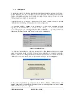
Page 17: ...al elements required for proper operation Figure 6 The Wireless Monitor is especially useful when positioning the Base Station with respect to the Sensor Section 3 Figure 6 Wireless Monitor The Wireless Tools utility wstools exe accessible by either desktop shortcut or by name under the program group for CDR Wireless Sensor software is intended to identify diagnose and resolve configuration and co...

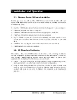
Page 18: ...Click Next after selecting the location where the software will be installed 7 Click Finish after the software is installed 3 2 USB Interface Positioning The Antenna Receiver and USB Interface can be surface wall or ceiling mounted as one unit docked or separately undocked to achieve the best performance To locate the units in their shipped docked position follow the steps below To locate them sep...

Page 19: ...checkmarks are green click Next 5 On the CDR Hardware screen Click the Test USB Interface button to test the Sensor s ability to send an image for display When the gray test pattern appears review it for clarity and contrast A good test pattern will have different shades of gray that are easy to distinguish Click the Test RF Environment button to test the amount of RF noise in the area where the S...

Page 20: ...is procedure before the Sensor is used the very first time and when you want to change the Sensor s channel to avoid interference 1 Remove the battery pack from the Sensor by sliding and lifting it away from Sensor 2 Place the Sensor with contacts side down into Sensor cradle located under the lid of the USB Interface Error Reference source not found 3 Run the CDR Wireless Tools utility to select ...

Reviews: