CDRPanX User Guide
B1051407 Rev. A
5
Refer to
Figure 4
for the following references.
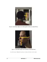
For proper patient positioning, use the pushbutton on the Control Panel to activate the
laser alignment beams — Mid-Sagittal Plane
(1)
, Frankfort Plane
(2)
, and Lateral Plane
for the center of the Focal Trough
(3)
.
Instruct the patient to grasp the patient handles
(4)
during the setup procedure as this will
help maintain correct positioning, even after the alignment adjustments are made. The
adjustment Knob
(5)
and Scale (
6
) are used during patient setup to change the distance
between the Bite Block (
7
) and the Vertical Carriage. Magnetic Brake button
(8)
is used
with the Handle
(9
) to adjust the Rotation unit vertically, along the Column.
Also accessible from the side of the CDRPanX are the Exposure switch
(10)
and
connector
(11),
On / Off switch
(12)
, and AC cable
(13)
for electrical service to the unit.
Figure 4. CDRPanX (Operator View)
(Locations of Asterisked Items are Approximate)
1
2
3
4*
6
8
5
13
10
12*
11
9
7

