CDRPanX User Guide
B1051407 Rev. A
iii
List of Figures
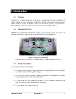
Figure 1. Panoramic Imaging Area ................................................................................................. 1
Figure 2. CDRPanX Simplified Block Diagram ............................................................................. 3
Figure 3. CDRPanX (Patient View) ................................................................................................ 4
Figure 4. CDRPanX (Operator View) ............................................................................................. 5
Figure 5. CDRPanX Control Panel ................................................................................................. 6
Figure 6. Correct Beam Alignment for Mid-Sagittal, Frankfort, and Lateral Planes .................... 12
Figure 7. Correct Beam Alignment for Frankfort and Lateral Planes ........................................... 12
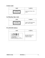
Figure 8. iPan HS USB Interface .................................................................................................. 18
Figure 9. Location of CDRPanX Power, Exposure, and Alignment Controls .............................. 20
Figure 10. Resend Option Selected in Panoramic Settings ........................................................... 25
Figure 11. Examples of Correct and Incorrect Patient Positioning ............................................... 26
Figure 12. Displayed Focal Trough Adjustments.......................................................................... 27
Figure 13. Examples of TMJ and Maxillary Sinus Exposures and Positioning ............................ 30
Figure 14. Operator Safety Zone ................................................................................................... 31
Figure 15. iPan HS Upgrade Utility .............................................................................................. 32
List of Tables
Table 1. CDRPanX Control Panel Description ............................................................................... 6
Table 2. CDRPanX Exposure Switch Description .......................................................................... 8
Table 3. Rotation Unit Positions and READY Light Indications.................................................... 9
Table 4. iPan HS USB Interface LED Indications ........................................................................ 19
Table 5. Voltage and Current Settings Based on Patient Type...................................................... 22
Table 6. Control Panel Error Codes .............................................................................................. 39
Table 7. Summary of CDRPanX Technical Data.......................................................................... 40
Table 8. Compliance Specifications .............................................................................................. 40
Table 9. Guidance and Manufacturer's Declaration - Electromagnetic Emissions ....................... 41
Table 10. Guidance and Manufacturer's Declaration - Electromagnetic Immunity ...................... 41
Table 11. Recommended Separation Distance Between Portable and Mobile RF Communications
Equipment and the CDRPanX System ................................................................................. 43

