background image

vi 

B1051407 Rev. A 

CDRPanX User Guide 

the workstation are virus-free and have been adequately  tested so they  will not  impact 
imaging applications after installation. 

Please refer to documentation provided by the PC manufacturer for important 
information about its safe operation and usage. 

Use Only Dedicated Host Computer(s) for Imaging Application(s)  

The host computer should be dedicated to imaging and not for general computing use. 
Also, prior to installing any software on dedicated workstation(s) and / or server(s), 
ensure that such software is virus-free and will not impact the operation and performance 
of imaging applications after installation. 

Do Not Touch Exposed Connectors on Non-Medical Equipment and the 
Patient at the Same Time  

When the CDRPanX product is in use, avoid touching exposed connectors on non-
medical electrical equipment and the patient at the same time. The human body is capable 
of conducting electrical current and may cause a shock hazard to patients if appropriate 
safety practices are not observed. 

Only Dentists or Authorized Designees Are Permitted to Operate the 
System  

To ensure the correct use of CDRPanX in a clinical environment, for purposes that 
correspond to its intended design and application, only dentists, or their designees, are 
authorized to operate the system. 

Use Only Manufacturer-Specified Parts and Accessories for Replacement 

Using accessories, transducers, and cables, other than those specified by the Schick 
Technologies as appropriate replacement parts for internal components, may result in 
increased emissions or decreased immunity of the CDRPanX system. 

The following cable configurations have been specified for the CDRPanX system. 

S

YSTEM 

C

OMPONENT


C

ABLE 

D

ESCRIPTION


C

ABLE 

R

OUTED TO


CDRPanX USB Sensor 

CAT-5 

iPan HS USB Interface 

iPan HS USB Interface 

USB 

USB port of compatible laptop or desktop PC 


Summary of Contents for CDRPanX

Page 1: ...CDRPanX User Guide Schick Technologies Inc 30 30 47th Avenue Long Island City NY 11101 USA 718 937 5765 718 937 5962 fax PART NUMBER B1051407 REV A ...

Page 2: ...sh CDR is a registered trademark of Schick Technologies Inc and is covered by US Patent Numbers 5 912 942 and 6 134 298 Additional patents are pending Trademark designations used by other manufacturers and sellers may appear in this document also Where Schick Technologies Inc was aware of a trademark claim that information has been printed in caps or initial caps ...

Page 3: ...on 20 5 1 Turning On the System 20 5 2 Ready Not Ready Indications 20 5 3 Turning Off the System 21 6 Panoramic Imaging 22 6 1 Panoramic Projection and Technique Factors 22 6 2 Patient Positioning and Panoramic Imaging 23 6 3 Using the Resend Option 25 6 4 Focal Trough Adjustments 27 6 5 TMJ Projections 28 6 6 Maxillary Sinus Projections 29 6 7 Operator Positioning and Panoramic Exposures 31 7 Usi...

Page 4: ...051407 Rev A CDRPanX User Guide 9 1 Visual Inspection 37 9 2 Periodic Maintenance 37 9 3 Scheduled Maintenance 38 Appendix A Error Codes 39 Appendix B Technical Data 40 Appendix C Cooling Curves 44 Index 45 ...

Page 5: ...ugh Adjustments 27 Figure 13 Examples of TMJ and Maxillary Sinus Exposures and Positioning 30 Figure 14 Operator Safety Zone 31 Figure 15 iPan HS Upgrade Utility 32 List of Tables Table 1 CDRPanX Control Panel Description 6 Table 2 CDRPanX Exposure Switch Description 8 Table 3 Rotation Unit Positions and READY Light Indications 9 Table 4 iPan HS USB Interface LED Indications 19 Table 5 Voltage and...

Page 6: ...dios and cellular phones To ensure proper operation the latter can be used only at a minimum distance of 6 feet 1 8m from any part of the equipment Any instrumentation or equipment for professional use located near CDRPanX must conform to Electromagnetic Compatibility regulations Non conforming equipment with known poor immunity to electromagnetic fields may not operate properly unless they are in...

Page 7: ...he CDRPanX system However before operating the system customers shall check it for any signs of physical damage or defect If detected contact your local distributor of Schick Technologies products for further instructions When No Longer Usable Dispose of System Components Properly The CDRPanX system is made of a variety of materials including iron aluminum lead copper plastics electronic component...

Page 8: ...lectrical equipment and the patient at the same time The human body is capable of conducting electrical current and may cause a shock hazard to patients if appropriate safety practices are not observed Only Dentists or Authorized Designees Are Permitted to Operate the System To ensure the correct use of CDRPanX in a clinical environment for purposes that correspond to its intended design and appli...

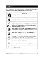
Page 9: ...e ETL mark is a Nationally Recognized Testing Lab NRTL marking and indicates conformance with UL 60601 1 and CAN CSA STD C22 2 NO 601 1 M90 Indicates that in the European Union at the end of product life this device must be disposed of in accordance with the requirements of the Waste Electrical and Electronic Equipment WEEE directive 2002 96 EC Indicates that under certain ambient environmental co...

Page 10: ...g Current Protective Earth Ground Power Off system disconnected from main power supply Power On system connected to main power supply Radiography Push Button Ionizing Radiation Indicator Inherent Filtration Fragile Handle With Care Humidity Limitation This End Up Do Not Turn Over Stacking Limit ...

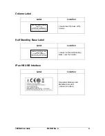
Page 11: ...ocations System Label 115V Shown Label Location Located near the patient handles Fuse Label Label Description Located near the fuse holder on the Vertical Carriage Generator Label Label Location Located near the X ray source also duplicated label ...

Page 12: ...abel Location Located near the patient handles Schick Technologies Inc Long Island City NY USA CDR PanX Collimator PN B4792500 Serial Number 1909LD0000 Manufactured September 2003 CERTIFICATION Product complies with radiation performance standards under the Federal Food Drug and Cosmetic act WARNING This x ray unit may be dangerous to patient and operator unless safe exposure factors and operating...

Page 13: ...Base near the Column iPan HS USB Interface Label Location Regulatory Markings and Manufacturer Label located on bottom CDR PanX Self Standing Base PN B4792220 Serial Number 1909SB0000 Manufactured September 2003 Schick Technologies Inc LIC NY USA CDR PanX Column Assembly PN B4792310 Serial Number 1909SC0000 Manufactured September 2003 Schick Technologies Inc LIC NY USA ...

Page 14: ... dispose of EEE waste equipment by handing it over to a designated collection point for the reuse or recycling of waste electrical and electronic equipment The separate collection and reuse or recycling of Electrical Electronic waste equipment will help to conserve natural resources and ensure that it is recycled in a manner that protects the environment and human health For more information about...

Page 15: ...e treatment and recycling information for each type of new EEE put on the market within one year of the date in which the equipment is put on the market Information will include the different EEE components and materials as well as the location of substances in these items The information will be provided as a printed document or in electronic media on CD ROM or by web download for example ...

Page 16: ...xiv B1051407 Rev A CDRPanX User Guide This page intentionally left blank ...

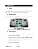
Page 17: ...es and acquires radiographic images at the dento maxillofacial region Figure 1 Figure 1 Panoramic Imaging Area 1 Maxillary Region 2 Dental Arch 3 Mandibular Region 4 Temporo Mandibular Joints TMJ 1 3 Notice to Installers It is the responsibility of the Installer To make sure that the line voltage specified by the manufacturer of the equipment is available and within the specified range To verify t...

Page 18: ... document Failure to maintain the equipment properly may result in personal injury or equipment damage and may relieve the manufacturer or its designated agent from responsibility arising from injury damage or non compliance To report promptly to the appropriate authority and the manufacturer or its designated agent any accident involving this medical device or any alteration in features and or pe...

Page 19: ...port 2 2 System Operation Panoramic imaging is performed by means of a narrow X ray beam that scans the dento maxillofacial area of the patient To ensure that this region is represented optimally on the resulting image proper understanding of the CDRPanX equipment and patient positioning is required Figure 3 and Figure 4 provide the location and identification of patient and operator views of the ...

Page 20: ...e following references CDRPanX consists of the following principal parts A Vertical Carriage 1 to which the power supply cord Exposure switch and digital imaging cable are connected moves vertically along the Column 2 permitting adjustments for the height of the patient A Rotation unit 3 consisting of a Control Panel 4 Digital Image Sensor system 5 and X ray Tube head 6 is connected to the Vertica...

Page 21: ... maintain correct positioning even after the alignment adjustments are made The adjustment Knob 5 and Scale 6 are used during patient setup to change the distance between the Bite Block 7 and the Vertical Carriage Magnetic Brake button 8 is used with the Handle 9 to adjust the Rotation unit vertically along the Column Also accessible from the side of the CDRPanX are the Exposure switch 10 and conn...

Page 22: ...nel Description No Item Description Additional References System Pushbuttons and Indicators 1 READY Indicates that system is ready to take an X ray 2 TEST Indicates test status condition is on off 3 Returns Rotation unit to ready position and resets errors 4 Activates the laser alignment beams for 15 seconds 5 Rotation Test Operates system without X ray source active 1 2 3 4 5 6 7 8 9 10 11 12 13 ...

Page 23: ... code display 12 mA mA Indicator Tube mA value displayed in Item No 11 13 mAs mAs Indicator mAs value displayed in Item No 11 14 SERVICE Service Indicator Service code displayed in Item No 11 15 Decrease or increase Adjusts value displayed in Item No 11 Panoramic Program Pushbuttons and Indicators 16 Adult selected 17 Child selected 18 Left side of dentition selected 19 Right side of dentition sel...

Page 24: ...el on the left X ray generator on the right when viewed facing the mirror 2 Ready Position Rotation unit positioned at rest at the start of its travel waiting for start of exposure 3 End of Exposure Position Rotation unit at rest at the end of its travel at the completion of an exposure 4 Patient Exit Position Rotation unit at rest with the Control Panel on the right X ray generator on the left wh...

Page 25: ... operation and can be used for reference in the paragraphs that follow Table 3 Rotation Unit Positions and READY Light Indications Rotation Unit Position Location READY Indicator Patient Entry OFF Ready ON Rotation Scan Finished BLINKING during X ray Tube cooling cycle Patient Exit BLINKING during X ray Tube cooling cycle ...

Page 26: ...position 2 4 3 Monitoring During Exposure During the exposure the Control System monitors movement of the Rotation unit and X ray generation according to the selected projection 2 4 4 Reset for Next Exposure After the exposure the Rotation unit comes to rest at the End of Exposure position Momentarily pressing either the Return button or Exposure switch at this time sends the Rotation unit to the ...

Page 27: ... alignment beams is a Class 1 Laser Operators are advised to avoid exposing their eyesight and that of their patients to unnecessary laser radiation by positioning the patient correctly and limiting the number of times the alignment beams are activated 2 4 10 Mid Sagittal Plane This is a vertical plane that is used to distinguish the right from left sides of the patient When set correctly the beam...

Page 28: ...e Figure 6 Correct Beam Alignment for Mid Sagittal Frankfort and Lateral Planes Figure 7 Correct Beam Alignment for Frankfort and Lateral Planes Laser Indications are Highlighted for Legibility on this Page and Elsewhere in this Document ...

Page 29: ...RPanX System 3 2 Requirements The recommended system requirements for CDR DICOM workstations are Compatible operating system refer to Section 2 2 512 MB RAM or higher Pentium IV 1 GHz or better or AMD 2 GHz or better 40 GB free disk space 1 EagleSoft and Patterson Imaging customers should refer to their user documentation for details 1 Storage requirements will vary depending on the patient volume...

Page 30: ...n 1 Exit CDR DICOM EagleSoft or Patterson Imaging if running and verify that the iPan HS Interface is NOT connected to the computer 2 Insert the iPan HS Interface Driver CD and click Install iPan HS Interface Driver when the start page is displayed 3 If prompted install Microsoft s NET framework 4 Click Next at the Welcome screen An example of the Welcome screen is shown below Continued on next pa...

Page 31: ...system Step Action 1 Click Install at the Ready to Install Screen 2 Click Finish at the end of the Installation An example of the Ready to Install the Program iPan HS Interface Driver screen is shown below An example of the InstallShield Wizard completed screen for installing the iPan HS Interface Driver is shown below Continued on next page ...

Page 32: ...e which illuminates the amber LED 2 If the Add New Hardware wizard starts and Windows asks to connect to Update select No not this time and click Next 3 Click next when the wizard asks to install software automatically 4 Click Finish and connect the CAT 5 cable to iPan HS interface An example of the Found New Hardware wizard is shown below An example of the Completing the Found New Hardware Wizard...

Page 33: ...n the iPan HS Upgrade Utility is displayed verify that all version numbers are in green If all version numbers are green the latest firmware has been installed successfully 3 If there are any items in the iPan HS Upgrade Utility with version information in red these must be upgraded by clicking on the button next to the item An example of the iPan HS Upgrade Utility is shown below Please note that...

Page 34: ...iPan HS USB Interface itself PANX HOST MACHINE iPAN HS USB INTERFACE PC WORKSTATION CAT 5 CABLE MAIN POWER USB CABLE LEDs are located on the exterior of the iPan HS USB Interface and provide power and status information A cable release access opening located at the top of the device can be used to disconnect the CAT 5 cable with the help of a small tool like a screwdriver The illustration and tabl...

Page 35: ... Status OFF ON USB cable connected Sensor not detected ON OFF Error condition ON ON USB cable connected Sensor detected Blinking Sensor is transmitting image to iPan HS USB Interface Blinking iPan HS USB Interface is transmitting image to host computer OFF OFF USB cable not connected if CDR is running or USB driver is not installed ...

Page 36: ...e displayed at the Control Panel Figure 5 X ray Tube Anode voltage is 60kV X ray Tube Anode current is 8 mA Adult Panoramic program is selected Figure 9 Location of CDRPanX Power Exposure and Alignment Controls 5 2 Ready Not Ready Indications Ready Not ready indications are displayed at the Control Panel Figure 5 A READY indicator is illuminated The Rotation unit is in the Ready position and ready...

Page 37: ...ops blinking and an audible alarm alerts the operator that usage can be resumed During the period when the Ready indicator is blinking only TMJ projections can be made all other panoramic programs are unavailable C READY indicator is not illuminated Press the Exposure switch or Return pushbutton to perform the Return function 5 3 Turning Off the System Turn off power at the CDRPanX On Off switch W...

Page 38: ...e 1 Pressing the Exposure switch under Test conditions causes the system to perform normally except that X rays are not generated The TEST indicator on the Control Panel is illuminated and the kVp and mA displays are set to zero to indicate that X rays are disabled in this mode 5 Once the testing session has been completed the Rotation unit can be brought to the ready position by pressing the Retu...

Page 39: ... note that in some cases class I and class II teeth cannot be completely shown on a single panoramic image For these patients expose the upper or lower jaw first then use the projection of the front teeth to represent the missed jaw either upper or lower Class I normal teeth 0 mm shift Class II protruded teeth 2 mm shift towards the vertical column Class III retruded teeth 2 mm shift away from the...

Page 40: ...swallow and keep the tongue lightly pressed to the palate and b remain calm and avoid movement until the end of the exposure The CDRPanX machine will indicate Error Code 11 if the Panoramic viewbox is not selected prior to starting panoramic motion To clear the error press the Exposure switch momentarily 15 When the message Ready to acquire image Activate panoramic motion now appears press the Exp...

Page 41: ...elected in Panoramic Settings An example of how the Resend feature is used is provided below 1 After taking a panoramic X ray a corrupted image is displayed 2 IMPORTANT Do not close CDR DICOM EagleSoft or Patterson Imaging as this will clear the image in the Sensor 3 Locate the Resend option on the Panoramic device property page CDR DICOM System Panoramic Settings EagleSoft or Patterson Imaging Fi...

Page 42: ...ser Guide Correct position Frankfort plane is horizontal Wrong position head tilted forward V shaped dental arch Wrong position head tilted backward flat dental arch Figure 11 Examples of Correct and Incorrect Patient Positioning ...

Page 43: ... PROBLEM The roots of the incisors fall outside the focal trough The front teeth appear blurred and proportionally narrower reduction ADJUSTMENT Use the Knob to move the patient backward away from the Column to correct INDICATION The laser beam dash line is anterior to the canine dotted line PROBLEM The roots of the incisors fall outside the focal trough The front teeth appear blurred and proporti...

Page 44: ...mitted during the middle part of the movementandtheaudiblealarmiscancelled 5 Create a new CDR exam with 2 viewboxes Click on the first viewbox then press and hold the Exposure switch to take the image The image displays in the first viewbox CDRPanX advances automatically to the TMJ Open Mouth projection 6 Press the Exposure switch or Return pushbutton to move the Rotation unit to the Patient Exit ...

Page 45: ...pport is below the nose The patient is to have normal occlusion with closed mouth Figure 13 3 Increase X ray tube voltage by 4 kV above what would be normally used for full panoramic images 4 Set the focal trough by 1 1 in 30 mm backwards away from the Column when compared with a typical position for a panoramic image 5 Click on the appropriate viewbox in CDR then press and hold the Exposure switc...

Page 46: ...30 B1051407 Rev A CDRPanX User Guide TMJ Exposures Closed Top and Open Bottom Maxillary Sinus Exposure Figure 13 Examples of TMJ and Maxillary Sinus Exposures and Positioning ...

Page 47: ...n and be ready to terminate the exposure ifnecessary atanytime The proper position for the operator during panoramic exposures is Behind the patient 10 feet 3 meters from the column in the designated safe zone as described in Figure 14 or Outside the exam area or operatory Figure 14 Operator Safety Zone SAFE ZONE FOR OPERATOR 10 FEET 3 METERS ...

Page 48: ... Module firmware upgrades A sample screen of the iPan HS Upgrade Utility is shown below Please note that the version numbers shown in the picture below are examples only and may differ from those reported for your system Figure 15 iPan HS Upgrade Utility The Refresh button on the utility can confirm the status of the system and can be useful before and after firmware upgrades Clicking the Refresh ...

Page 49: ...rtifacts or may be compeletely blank and suggests a problem with the USB cable USB port or possibly the iPan HS USB Interface itself USB Interface Test Perform the following steps to start the USB Interface test procedure Step Action 1 IMPORTANT Close CDR DICOM EagleSoft or Patterson Imaging program if running before continuing with next step 2 Verify that iPan HS USB Interface is connected to hos...

Page 50: ...elow USB Interface Firmware Upgrade Perform the following steps to start the USB Interface firmware upgrade procedure Step Action 1 IMPORTANT Close the CDR DICOM EagleSoft or Patterson Imaging program if running before continuing with next step 2 Verify that iPan HS USB Interface is connected to host computer 3 Start the iPan HS Upgrade Utility 4 If the firmware version number is listed in red cli...

Page 51: ...e following steps to start the Sensor Module firmware upgrade procedure Step Action 1 IMPORTANT Close CDR DICOM EagleSoft or Patterson Imaging program if running before continuing with next step 2 Verify that iPan HS USB Interface is connected to host computer 3 Start the iPan HS Utility 4 If the firmware version number is listed in red click the Firmware Version button to upgrade 5 If the CPLD ve...

Page 52: ...ment causing potential damage to internal electrical and mechanical components Never use solvents such as alcohol and Trichloroethylene corrosive or abrasive substances when cleaning Clean and disinfect parts of the CDRPanX system that touch the patient Clean any dust that may have accumulated in the output window of each laser source When the surfaces that were cleaned have dried sufficiently con...

Page 53: ...Always disconnect the main power supply before cleaning the system Any defect or malfunction should be corrected immediately by qualified personnel with adequate training Tasks to be performed regularly include the following To clean CDRPanX parts and surfaces use isopropyl alcohol wiped or sprayed or mild soap taking care not to allow any liquid to seep into the equipment Plastic covers can be wi...

Page 54: ...cific lubrication of movable parts has to be done at least every two years of operation Check that the labels are intact readable and adhere well to the surfaces on which they are positioned Check that all of the cables that connect equipment in the CDRPanX system are undamaged Check that there is no external damage to the CDRPanX equipment which could compromise its ability to operate safely and ...

Page 55: ...successful 21 Exposure switch released after X ray emission but rotation motor movement was not complete 23 Rotation unit steps do not match in half of the track 25 Rotation unit steps do not match in half of the track 28 Rotation unit steps do not match at the end of the track 31 Rotation unit does not move 33 Tube filament heating current active during off status 34 X ray tube current active dur...

Page 56: ...3 cm from 2 9 ft to 5 95 ft 88 5 to 181 5 cm Vertical Movement Manual Adjustment Patient Positioning Manual Carriage Adjustment Positioning Lasers Lateral mid sagittal frankfort Centering Reference Chin rest with bite stick Focus Film Distance 1 67 ft 51 cm Exposure time 19 s Projections Adult 19 s Children 15 s Half Left 10 s Half Right 10 s Frontal Teeth 8 s TMJ opened and closed mouth 4 x 4 s F...

Page 57: ...stem must ensure that it is used in such an environment Emissions Test Compliance Electromagnetic Environment RF emissions CISPR 11 Group 1 The CDRPanX system uses energy only for its internal function Therefore its RF emissions are very low and are not likely to cause any interference in nearby electronic equipment RF emissions CISPR 11 Class B Voltage fluctuations flicker emissions IEC 61000 3 3...

Page 58: ...at of a typical commercial or hospital environment If the user of the CDRPanX system requires continued operation during mains interruptions it is recommended that the CDRPanX system be powered from an uninterruptible power supply or battery NOTE UT is the AC mains voltage prior to application of the test level Power frequency 50 60 Hz magnetic field IEC 61000 4 8 3A m 3A m Power frequency magneti...

Page 59: ...RPanX System b Over the frequency range 150 kHz to 80 MHz field strengths should be less than 3 V m Table 11 Recommended Separation Distance Between Portable and Mobile RF Communications Equipment and the CDRPanX System PLEASE NOTE The CDRPanX System is intended for use in an electromagnetic environment in which radiated RF disturbances are controlled The customer or user of the CDRPanX System can...

Page 60: ...44 B1051407 Rev A CDRPanX User Guide Appendix C Cooling Curves ...

Page 61: ... Exposure 10 High Voltage Setting 10 Monitoring During Exposure 10 Reset for Next Exposure 10 Setup for Exposure 8 Controls and LED Indicators 18 Cooling Curves 44 D Dedicated Host Computer vi Do Not Touch Exposed Connectors vi E Ensure CDRPanX C System Operates Optimally v Error Codes 39 Table Describing 39 Error Handling 11 Exposure 10 Exposure Switch Table Describing 8 F Federal Law Restriction...

Page 62: ...ns 20 Requirements 13 Reset for Next Exposure 10 Reset Function 11 RF Interference iv S Safety Issues Dedicated Host Computer vi Do Not Touch Exposed Connectors on Non Medical Equipment and the Patient at the Same Time vi Ensure CDRPanX C System Operates Optimally v Preventive Maintenance v Restriction for Sale iv RF interference iv Sensor Module Upgrade 35 Setup for Exposure 8 Summary of Technica...

Reviews: