Operating Manual 90° ACTUSAFE CMF(S)QT
OM-ENGLISH-Failsafe-QT-16xx-V2.00-2022.03.01
7 Commissioning
7.2.5
Required torque on the handwheel
The following table shows the maximum torque applied to the handwheel for the different actuator sizes.
Type
Max. handwheel torque
[
Nm
]
Handwheel
diameter
[
mm
]
In Failsafe direction
Counter Failsafe
direction
CM03F(S)QT30
4
8,5
140
CM03F(S)QT60
4
14,5
140
CM06F(S)QT100
8
32
200
CM06F(S)QT200
8
28,5
200
CM06F(S)QT300
8
31
200
CM06F(S)QT500
8
32
200
The force on the handwheel was calculated for one-handed operation. With two-hand operation, the value per hand is
halved. The maximum force may be exceeded by 20% in manual mode.
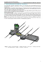
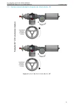
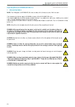
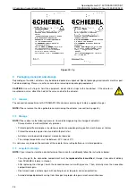
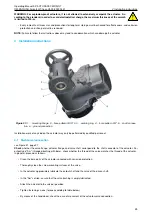
The direction of rotation and the maximum handwheel torque are written on the handwheel label, as shown on figure above.
7.3
Mechanical default setting, preparation
See operating manual ACTUSMART CM.V1.2, section 5.3, page 30
7.4
Setting the end positions
See operating manual ACTUSMART CM.V1.2, section 5.5, page 31
7.5
Setting the mechanical end stop
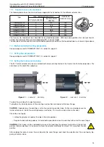
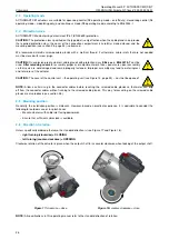
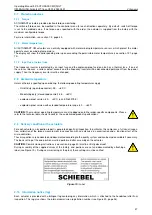
The 90° Failsafe actuator only has one limited mechanical end stop that limits the travel at the Failsafe end position. The
end stop is at the end of the spring cup.
Figure 8:
1. . . Locknut, 2. . . End stop
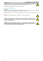
Figure 9:
1. . . Locknut, 2. . . End stop
To adjust the end stop, first undo the locknuts.
To lengthen the stroke by means of the end stop, unscrew the end stop out of the cover flange.
CAUTION:
Upon delivery, the end stop is set to the maximum possible stroke. Further unscrewing causes no
further extension of stroke; the end stop becomes ineffective. This must be ruled out no matter what.
Check the end stop by:
• Letting the actuator run against the stop in Failsafe operation.
• Despite the locknut being undone, it should not be possible to screw the end stop further into the cover flange.
CAUTION:
If the stroke is to be shortened by means of the end stop, the actuator must not be in the Failsafe
position. Before adjusting, it is necessary to move the actuator electrically for at least 10% away from the end
position.
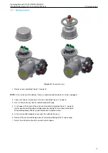
After undoing the locknut, screw the end stop into the cover flange, and check the adjustment of the end stop by trig-
gering a Failsafe stroke.
15

