Operating Manual 90° ACTUSAFE CMF(S)QT
OM-ENGLISH-Failsafe-QT-16xx-V2.00-2022.03.01
4 Installation instructions
WARNING: For explosion-proof actuators, it is not allowed to extensively overpaint the actuator. Ac-
cording to the standard, in order to avoid electrostatical charge, the maximum thickness of the varnish
is limited to 200
µ
m.
• Every 6 months, all measures and precautions for long-term storage must be checked for effectiveness, and corrosion
protection and silica gel must be renewed.
NOTE:
Failure to follow the instructions above may lead to condensation which can damage the actuator.
4
Installation instructions
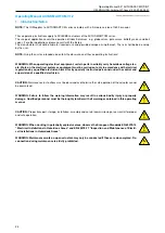
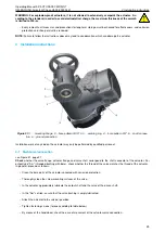
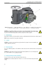
Figure 21:
1. . . mounting flange, 2. . . bore pattern G0/F10, 3. . . centring ring, 4. . . bore pattern F07, 5. . . shaft connec-
tion, 6. . . ground connection
Installation work of any kind on the actuator may only be performed by qualified personnel.
4.1
Mechanical connection
Check
whether the valve flange, actuator flange and valve shaft correspond to the shaft connector of the actuator. For
output type "Am" (threaded bushing with bore), check whether the thread of the valve matches the thread of the actuator.
In general, proceed as follows:
• Clean the bare parts of the actuator uncoated with corrosion protection.
• Thoroughly clean the screw mounting surfaces of the valve.
• In the actuator, appropriately lubricate the output shaft and the valve of the driven shaft.
• In the "Am" version, ensure that the valve bushing is amply lubricated.
• Attach the actuator to the valve or gearbox.
• Tighten fastening screws (torque according to table below).
• By means of the handwheel, check the ease of movement of the actuator-valve connection.
29

