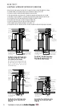
A
C
C
D
B
B
B
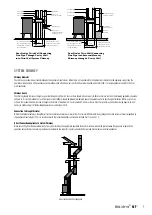
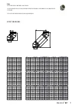
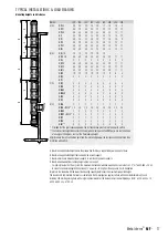
A Maximum supportable height above Tee piece when chimney is supported by wall support at base�
B Maximum supportable height that can be borne by wall support�
C Maximum distance between lateral supports i�e� wall bands and wall supports�
D Maximum allowable free standing height above last support�
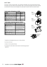
- For non-vertical parts of flue system the maximum distance between two wall bands i�e� brackets is 2,5* m (*ø 450-600 = 3,5 m)
- In case of a condensing application a slope of 3° upwards, starting from the appliance, has to be applied
Important: the product with the lowest load bearing capacity determines the maximum supported height�
The clearance to combustible materials, as indicated in the CE-designation, applies to flues with a nominal diameter up to and
including 300 mm� Regarding flues with a larger nominal diameter, the clearance must be multiplied by a factor: ø 350 - ø 450 x 1�5,
ø 500 - ø 600 x 2, > ø 700 x 4�
TYPICAL INSTALLATIONS & LOAD BEARING
Mounting heights and distances
Ø(mm)
100 130 150 180 200 250 300 350 400
A (m)
MFT 45
30
30
25
20
20
17
10
10
9
MFT
87
30 30 30 25 25 20 15 15 12
MFT
90
30 30 30 25 25 20 15 15 12
MFI
30 30 30 25 25 20 15 15 12
MFTI
30 30 25 20 20 17 10 10 9
MFTR
30 30 30 25 25 20 15 15 12
MFTRS
30 30 30 25 25 20 15 15 12
MFNL
30 30 30 25 25 20 15 15 12
B
(m) MFOL1/2
10 10 10 10 10 10 - - -
MFOH
2/4 40 40 40 35 35 25 20 17 17
MFSA
5 5 5 5 5 5 5 5 5
MFAPO
40 40 40 35 35 25 20 17 17
MFAPU
40 40 40 35 35 25 20 17 17
MFBTS
40 40 40 35 35 25 20 17 17
MFMO
10 10 10 10 10 10 8 6 4
MFDQ
3 3 3 3 3 3 3 3 3
MFTS
- - - - - - - - -
C
(m) MFDQ
4 4 4 4 4 4 4 4 4
MFMB
4 4 4 4 4 4 4 4 4
MFMBV
4 4 4 4 4 4 4 4 4
MFMBAH 3 3 3 3 3 3 3 3 3
MFMO
4 4 4 4 4 4 4 4 4
MFVQ
4 4 4 4 4 4 4 4 4
D
(m) MFMB
2 2 2 2 2 2 2 2 2
MFMB + MFSK* 2,5
2,5
2,5
2,5
2,5
2,5 2,5
2,5
2,5
MFMBV
2 2 2 2 2 2 2 2 2
MFMBV + MFSK* 3
3
3
3
3
3
3
3
3
MFDQ
2 2 2 2 2 2 2 2 2
MFMO
2 2 2 2 2 2 2 2 2
MFBT**
3 3 3 3 3 3 3 3 3
* Provided that the joints above and below the last connection point are reinforced with a MFSK�
** The construction height B becomes 30% lower, when making use of a MFBT� Guy-wires are to be fixed
at an angle of 45 degrees, at 2/3 of the freestanding height�
All joints above the last connection point and the joint directly below the last connection point have to be
reinforced with a MFSK�
17
Metaloterm
®
MF
-

