
NL 2:3 1:1,5
GB 1:2
BE 13:15 1:1,15
FR 2:3 1:1,5
DE
3:5
1:1,7
CH 1:1
IT
2:3
1:1,5
FI 11:18 1:1,64
NO 8:11 1:1,375
LV 1:2
PL 5:8 1:1,6
CZ 2:3 1:1,5
GR 2:3 1:1,5
CY 3:5 1:1,7
SE 10:16 1:1,6
DK 28:37 1:1,32
AT 2:3 1:1,5
HU 1:2
RO 2:3 1:1,5
RS 2:3 1:1,5
BG
3:5
1:1,7
IE 1:2
LU
1:2 (of 3:5)
EG
2:3
1:1,5
NZ 1:2
RU 2:3
MD 1:2
EU 2:3 1:1,5
Land Verhouding
vlag vlag+outline kleurcodes
Vlaggen (v.2015)
C-M-Y-K:
0-84-77-32
C-M-Y-K:
0-0-0-0
Pantone
032-C
C-M-Y-K:
0-0-0-0
C-M-Y-K:
76-50-0-46
C-M-Y-K:
100-72-0-18.5
C-M-Y-K:
0-0-0-0
C-M-Y-K:
0-91-76-6
C-M-Y-K:
100-72-0-18.5
C-M-Y-K:
0-0-0-0
C-M-Y-K:
0-91-76-6
C-M-Y-K:
0-0-0-100
C-M-Y-K:
0-15-95-0
C-M-Y-K:
0-90-80-5
C-M-Y-K:
100-70-0-5
C-M-Y-K:
0-0-0-0
C-M-Y-K:
0-90-86-0
C-M-Y-K:
0-0-0-100
C-M-Y-K:
0-100-100-0
C-M-Y-K:
0-12-100-5
Pantone
144-C
Pantone
336-C
C-M-Y-K:
0-0-0-0
C-M-Y-K:
0-100-100-0
C-M-Y-K:
0-0-0-0
C-M-Y-K:
100-0-100-45
C-M-Y-K:
0-0-0-0
C-M-Y-K:
0-100-100-0
C-M-Y-K:
100-70-0-10
C-M-Y-K:
0-10-95-0
C-M-Y-K:
0-90-80-5
Pantone
186-C
Pantone
116-C
C-M-Y-K:
0-0-0-100
C-M-Y-K:
100-70-0-10
C-M-Y-K:
0-10-95-0
C-M-Y-K:
0-90-80-5
C-M-Y-K:
100-70-0-10
C-M-Y-K:
0-10-95-0
C-M-Y-K:
0-90-80-5
Pantone
347-C
Pantone
151
RGB:
255-255-255
RGB:
0-150-110
RGB:
214-38-18
Pantone
032-C
C-M-Y-K:
0-0-0-0
Pantone
299
C-M-Y-K:
100-56-0-18.5
C-M-Y-K:
0-0-0-0
Pantone Red
032 U
C-M-Y-K:
0-0-0-0
Pantone Red
281 U
C-M-Y-K:
25-96-84-19
C-M-Y-K:
0-0-0-0
Pantone
186-C
C-M-Y-K:
0-0-0-0
C-M-Y-K:
0-0-0-0
Pantone
348-C
#: D4 21 3D
ca.10-96-71-1
#: E9 E8 E7
NCS
0580-Y10R
NCS
4055-R95B
Pantone
281 U
Pantone Red
032 U
C-M-Y-K:
0-0-0-0
C-M-Y-K:
ca.98-99-22-14
C-M-Y-K:
0-0-0-0
Pantone
186-C
C-M-Y-K:
0-0-0-0
C-M-Y-K:
100-80-0-0
C-M-Y-K:
0-0-100-0
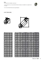
3/2
2/9
1
1
3/2
30°
2/3
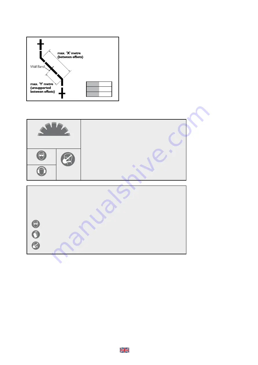
Max Offset Info (in same plane)
Int Ø
X (m)
Y (m)
125-200
3
1.5
29
HEALTH & SAFETY INSTRUCTION
Many building products, including chimney elements are manufactured using natural
raw materials which contain proportions of crystaline quartz.
During the mechanical processing of products, such as cutting and drilling, quartz
dust is released which can get into the lungs.
With higher levels of exposure over longer periods this may result in damage to
the lungs (silicosis) and as a consequence of the silicosis disease, to an increased
risk of lung cancer.
THE FOLLOWING PROTECTIVE MEASURES ARE TO BE TAKEN
• When cutting and drilling, a P3/FFP3 respiratory protection mask is to be worn.
• In addition, wet-cutting equipment or equipment with dust extraction should be used.
Protection measures are required when
cutting and drilling. Wet-cutting or dust
extraction should be used.
Eye Protection
Ear Protection
P3/FFP3
Respiratory
Protection Mask
HAZARDS FOR PEOPLE AND THE ENVIRONMENT
Mineral wool insulation materials in this group of products can release fine fibres which may have carcinogenic effects in the
lungs. If inhaled, fibres can get into the body and cause damage to health. Larger fibres or fragments of fibres can cause irritation
(itching) of the skin, the upper airways and the eyes!
PROTECTION MEASURES AND SAFE PRACTICE
Avoid contact with the skin!
After finishing work, rinse off dust with water and change your clothes. wash exposed areas of skin thoroughly with soap and
if necessary use a skin care product!
Eye Protection:
Hand Protection:
Breathing:
When working overhead and where large amounts of dust are produced, wear goggles
with side protection.
Protective gloves, e.g. in leather or nitrile-coated cotton.
For low-level activities (exposure category E1/E2) the use of half or quarter masks with
P2 filters (white) or FFP2 particle filtering half masks is recommended.
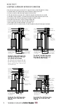
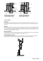
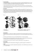
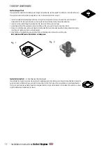
22.
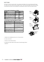
Example of a design with a double-
walled connecting flue pipe.
23.
Finished installation.
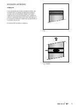
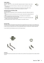
OFFSET INSTALLATION
HEALTH & SAFETY
HEALTH AND SAFETY PRECAUTIONS
Special care must be taken when installing the chimney system such that the requirements of the Health and Safety at Work Act are met�
Handling
Adequate facilities must be available for loading, unloading and site handling�
Fire Cement
Some types of fire cement are caustic and should not be allowed to come into contact with the skin� In case of contact wash immediately with plenty of water�
Asbestos
This chimney product contains no asbestos� If there is a possibility of disturbing any asbestos in the course of installation then please seek specialist guidance and use
appropriate protective equipment�
18
- Installation instructions
United Kingdom


