
7
SYSTEM CHIMNEY
Chimney Diameter
The chimney size should be as recommended by the appliance manufacturer. Where there is a requirement for a flue
diameter smaller than the appliance spigot, then the operational requirements of the appliance and the configuration of
the flue must satisfy the flue sizing requirements of EN13384-1 for single appliances, and EN13384-2 for multi appliances.
Chimney Route
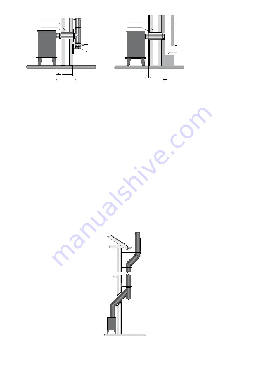
The chimney should remain as straight as possible through its vertical run to assist flow. Should it be necessary to offset
a chimney run then the following guidelines should be adhered to:
It is recommended that a vertical run of at least 600mm should be allowed immediately above the appliance prior to
any change of direction. Within a system, on all fuels, there should be no more than 4 changes of direction of maximum
45°. Factory made 90° bends or tees within the system may be treated as being equal to two 45° bends (as per
Document J of the Building Regulations issued October 2010).
Connection to Draught Diverter
Where the appliance features a draught diverter the connection should rise vertically from it for at least 600mm
before any change of direction (unless otherwise specified by the appliance manufacturer). This is in accordance with
the recommendations contained in BS 5440 Part 1 section 6.1.4
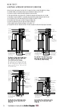
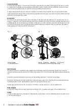
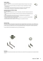
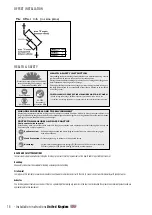
Direct Connection Appliance to System Chimney
When connecting from the appliance directly to a system chimney, the appropriate appliance connector must be used
and the joint between the appliance spigot and the appliance connector must be securely caulked and sealed with non
asbestos rope (or suitable alternative) and fire cement on solid fuel appliances.
ICID Plus direct connection
from appliance.
6
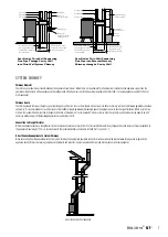
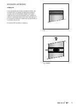
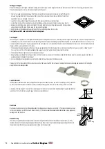
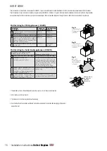
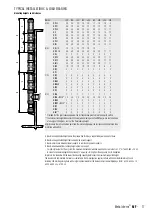
Top Outlet Twin Wall Connecting
Flue Pipe into Re-lined Masonry
Chimney
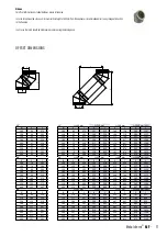
Rear Outlet Twin Wall Connecting
Flue Pipe Through Cavity Wall
into Twin Wall System Chimney
Rear Outlet Twin Wall Connecting
Flue Pipe into Re-lined Masonry
Chimney
Rear Outlet Twin Wall Connecting
Flue Pipe into External Masonry
Chimney through a Cavity Wall
For minimum distance for
this configuration check
manufacturers distance
to combustibles
Measured from back
of appliance to outside
surface of chimney
Measured from back
of appliance to liner
of masonry chimney
Twin Wall
Chimney System
300
Wall Support
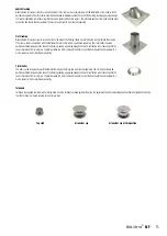
Tee Cap for
Debris Collection/
Cleaning Access
Wall Sleeve
Trim Collar
Cavity Wall
Wall Band
450mm MAX
300
450mm MAX
External Masonry
Chimney System
Inspection/
Cleanout Door
Cavity Wall
Wall Sleeve
Trim Collar
Debris
Collector
Wall Sleeve
Trim Collar
100
100
225 square
(9” x 9”)
Flexible Twin Wall
Chimney Liner
Chimney Wall
Support Bracket
Swept Elbow
Sweep access
Tee Piece
Single Wall to
Flex Connector
450mm
MAX
Measured from
back of appliance
to flue liner
Wall Support
Measured from back
of connecting flue
pipe to outside
surface of chimney
Tee Cap for
Debris Collection/
Cleaning Access
Twin Wall
Chimney System
Solid Wall
Inspection Bend
Wall Sleeve
Trim Collar
600 min
225
For minimum distance for
this configuration check
manufacturers distance
to combustibles
No further
bends allowed
on this
configuration
Wall Band
450mm MAX
Measured from back
of connecting flue
pipe to outside
surface of chimney
Tee Cap for
Debris Collection/
Cleaning Access
Twin Wall
Chimney System
Solid Wall
Inspection Bend
Wall Sleeve
Trim Collar
225
Wall Support
Wall Band
450mm MAX
600 min
For minimum distance for
this configuration check
manufacturers distance
to combustibles
No further
bends allowed
on this
configuration
Flexible Twin Wall
Chimney Liner
Inspection/
Cleanout Door
Inspection Bend
Wall Sleeve
Trim Collar
Chimney Wall
Support Bracket
Tee Piece
Tee Cap for
Debris Collection/
Cleaning Access
Single Wall to
Flex Connector
225 square
(9” x 9”)
450mm
MAX
For minimum distance for
this configuration check
manufacturers distance
to combustibles
For minimum distance for
this configuration check
manufacturers distance
to combustibles
For minimum distance for
this configuration check
manufacturers distance
to combustibles
Measured from back
of connecting flue pipe
to flue liner
No further
bends allowed
on this
configuration
600 min
100
100
For minimum distance for
this configuration check
manufacturers distance
to combustibles
Measured from back
of appliance to outside
surface of chimney
Measured from back
of appliance to liner
of masonry chimney
Twin Wall
Chimney System
300
Wall Support
Tee Cap for
Debris Collection/
Cleaning Access
Wall Sleeve
Trim Collar
Cavity Wall
Wall Band
450mm MAX
300
450mm MAX
External Masonry
Chimney System
Inspection/
Cleanout Door
Cavity Wall
Wall Sleeve
Trim Collar
Debris
Collector
Wall Sleeve
Trim Collar
100
100
225 square
(9” x 9”)
Flexible Twin Wall
Chimney Liner
Chimney Wall
Support Bracket
Swept Elbow
Sweep access
Tee Piece
Single Wall to
Flex Connector
450mm
MAX
Measured from
back of appliance
to flue liner
Wall Support
Measured from back
of connecting flue
pipe to outside
surface of chimney
Tee Cap for
Debris Collection/
Cleaning Access
Twin Wall
Chimney System
Solid Wall
Inspection Bend
Wall Sleeve
Trim Collar
600 min
225
For minimum distance for
this configuration check
manufacturers distance
to combustibles
No further
bends allowed
on this
configuration
Wall Band
450mm MAX
Measured from back
of connecting flue
pipe to outside
surface of chimney
Tee Cap for
Debris Collection/
Cleaning Access
Twin Wall
Chimney System
Solid Wall
Inspection Bend
Wall Sleeve
Trim Collar
225
Wall Support
Wall Band
450mm MAX
600 min
For minimum distance for
this configuration check
manufacturers distance
to combustibles
No further
bends allowed
on this
configuration
Flexible Twin Wall
Chimney Liner
Inspection/
Cleanout Door
Inspection Bend
Wall Sleeve
Trim Collar
Chimney Wall
Support Bracket
Tee Piece
Tee Cap for
Debris Collection/
Cleaning Access
Single Wall to
Flex Connector
225 square
(9” x 9”)
450mm
MAX
For minimum distance for
this configuration check
manufacturers distance
to combustibles
For minimum distance for
this configuration check
manufacturers distance
to combustibles
For minimum distance for
this configuration check
manufacturers distance
to combustibles
Measured from back
of connecting flue pipe
to flue liner
No further
bends allowed
on this
configuration
600 min
100
100
SYSTEM CHIMNEY
Chimney Diameter
The chimney size should be as recommended by the appliance manufacturer� Where there is a requirement for a flue diameter smaller than the appliance spigot, then the
operational requirements of the appliance and the configuration of the flue must satisfy the flue sizing requirements of EN13384-1 for single appliances, and EN13384-2 for
multi appliances�
Chimney Route
The chimney should remain as straight as possible through its vertical run to assist flow� Should it be necessary to offset a chimney run then the following guidelines should be
adhered to: It is recommended that a vertical run of at least 600mm should be allowed immediately above the appliance prior to any change of direction� Within a system, on
all fuels, there should be no more than 4 changes of direction of maximum 45°� Factory made 90° bends or tees within the system may be treated as being equal to two 45°
bends (as per Document J of the Building Regulations issued October 2010)�
Connection to Draught Diverter
Where the appliance features a draught diverter the connection should rise vertically from it for at least 600mm before any change of direction (unless otherwise specified by
the appliance manufacturer)� This is in accordance with the recommendations contained in BS 5440 Part 1 section 6�1�4
Direct Connection Appliance to System Chimney
When connecting from the appliance directly to a system chimney, the appropriate appliance connector must be used and the joint between the appliance spigot and the
appliance connector must be securely caulked and sealed with non asbestos rope (or suitable alternative) and fire cement on solid fuel appliances�
direct connection from appliance
7
Metaloterm
®
MF
-