background image


Sirius Operating Manual 


Sirius Operating Manual  

Page | 

4


INITIAL OPERATION .................................................................................................................... 22


Using the appliance the first time.............................................................................................. 22


Running in the appliance .......................................................................................................... 22


Information on noises ............................................................................................................... 22


Information on combustion chamber lining .................................................................................... 22


HEATING CORRECTLY ............................................................................................................... 23


Fuel loading ............................................................................................................................. 24


Heating in the transitional period .............................................................................................. 24


CLEANING AND MAINTENANCE ............................................................................................ 24


How to clean the heating door .................................................................................................. 25


Cleaning with an ash vacuum ................................................................................................... 25


Cleaning varnished surfaces .................................................................................................... 25


Cleaning the window ................................................................................................................ 26


Cleaning the combustion chamber ........................................................................................... 26


Grate and ash holder ................................................................................................................ 26


Flue gas ducts .......................................................................................................................... 26


CLEAN AIR ACT ........................................................................................................................... 27


The Clean Air Act 1993 and Smoke Control Areas ................................................................... 27


TROUBLESHOOTING .................................................................................................................. 28


TECHNICAL DATA ....................................................................................................................... 29


Type testing / Quality seal ........................................................................................................ 29


CE MARKING ............................................................................................................................... 30


Summary of Contents for Sirius 1

Page 1: ...Operation Manual Version 1 2 26 08 20 Sirius Stove Operating Manual Schiedel Chimney Systems Crowther Road Crowther Industrial Estate Washington Tyne Wear NE38 0AQ Tel 0191 4161150 info uk schiedel com ...

Page 2: ...tore this instruction manual in a safe location 8 Liability 8 Improper use 8 Information on legal regulations 9 Only use suitable fuel 9 Chimney requirements 9 Regular cleaning and maintenance work 9 Spare parts and accessories 9 Original condition 9 Correct installation entering service 9 Sufficient supply of fresh air 9 What to do in the event of a chimney fire 10 TRANSPORT PACKAGING 11 Modes of...

Page 3: ...Chimney 14 Room sealed operation 15 Connection methods 15 Changing the supply air feed exhaust extraction pipe 16 Exhaust pipe from the rear 17 Supply air feed from the rear 18 Supply air feed from below 18 OPERATION 19 Accessories provided 19 Heating door lock 19 Setting for the combustion air 19 Setting for the Air Supply Lever to prevent flow of combustion air 19 Device set to 0 20 Heat setting...

Page 4: ...Y 23 Fuel loading 24 Heating in the transitional period 24 CLEANING AND MAINTENANCE 24 How to clean the heating door 25 Cleaning with an ash vacuum 25 Cleaning varnished surfaces 25 Cleaning the window 26 Cleaning the combustion chamber 26 Grate and ash holder 26 Flue gas ducts 26 CLEAN AIR ACT 27 The Clean Air Act 1993 and Smoke Control Areas 27 TROUBLESHOOTING 28 TECHNICAL DATA 29 Type testing Q...

Page 5: ...handle for the heating door Door for the wood storage compartment Cleaning port Door seal Lateral heating door window only on SIRIUS 3 Combustion chamber lining made from fireclay Ash tray Wood door pocket opening pressure point Cast iron ash grate Ember catching device made from cast iron Grate riddling mechanism Combustion air flow lever Door closing mechanism Wood storage compartment Set of scr...

Page 6: ... delivery 1 Cover plate for top flue pipe entry 2 Cover for the upper central air supply 3 Seal for the central supply air 4 Ring for the top plate 5 Top plate cover 6 Connecting element for the central air inlet 100 mm 7 Inlay board for the base plate 8 Hook for the revolving grate 9 Protective glove Device dimensions Lateral heating door window only ...

Page 7: ...place any objects which are not resistant to heat on the stove It is also prohibited to dry clothes on the stove Clothes or similar items must be placed a sufficient distance away from the stove when drying Caution children playing Please note that the surface of the stove can become extremely hot when the device is being used Make sure children are aware of the hazard and keep them away from the ...

Page 8: ...gn faults are proven to exist The manufacturer shall bear no liability if the device is not used as intended the device is not operated as intended maintenance work is inadequate the spare parts used are not original structural changes have been made to the device Improper use Using the device in any other way than that intended may result in life threatening injuries and large scale material dama...

Page 9: ...ocked if the device is going to be stoked after it has not been used for a long time Regular cleaning and maintenance work The stove including all of the system components connected e g the chimney must be cleaned and serviced on a regular basis in order to make sure that the device remains functional and efficient Spare parts and accessories Only use original spare parts and accessories Original ...

Page 10: ...esh air must be fed into the room from outdoors if need be Combustion air inlets must not be closed What to do in the event of a chimney fire If the stove chimney or connecting element is not cleaned on a regular basis or if unsuitable fuel is used residue may catch fire This may cause a chimney fire Keep the heating door closed and set the air regulator to the lowest possible setting Keep any com...

Page 11: ...s of transport The device may only be transported using vehicles with a sufficient load bearing capacity Safety during transportation The device is secured on the pallet using transport locking screws in the wood storage compartment see image Transport on pallets Transport the device to the installation site on a pallet Remove the equipment used as a transport lock in the wood storage compartment ...

Page 12: ...ardwood can be stored for 3 years under cover The following table shows the impact of the water content of wood on its heat value Refuelling on to a low fire bed If there is insufficient burning material in the firebed to light a new fuel charge excessive smoke emission can occur Refuelling must be carried out onto a sufficient quantity of glowing embers and ash that the new fuel charge will ignit...

Page 13: ...he guarantee PLEASE NOTE If unauthorized and low quality fuels are used we reserve the right to withdraw the guarantee and warranty claims INSTALLATION Minimum distances to combustibles The stove is designed to be a free standing indoor device It must be installed at the following distances from heat sensitive components wood partitions furniture decorative fabrics Distances SIRIUS 1 mm SIRIUS 3G ...

Page 14: ...rpets a superimposed hearth made from toughened glass or any other non flammable material should be used This base must have the following minimum dimensions with the opening of the combustion chamber as the starting point Front 225mm Side 150mm Inlay board for the base plate please see accessory component 7 provided install after the final location for the stove has been chosen Chimney It must be...

Page 15: ... compact design and self closing doors If the structural conditions mean that room sealed operation is impossible it is also possible for the SIRIUS stove to draw the combustion air from the room where it has been installed non room sealed operation In this case the installer should ensure that the air supply in the room where the device has been installed is sufficient Connection methods 1 On sta...

Page 16: ...t extraction pipe as standard Tools required to make any alterations Allen key magnetic Allen wrench 1 Remove the top plate and take off the outer air inlet and inner flue tube supports 2 Stick the cover for the upper central supply air feed accessory part 2 with the seal for the central supply air feed accessory part 3 to the inner and outer edge and attach to the stove ...

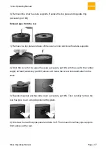
Page 17: ...ner flue tube supports 2 Stick the cover for the upper flue pipe accessory part 1 with the seal for the central supply air feed accessory part 3 above and below the screw holes and attach to the stove 3 Replace top plate and top plate cover accessory part 5 Then carefully remove the rear flue pipe cover using diagonal cutting pliers 4 Unscrew the rear flue pipe panel and take it off Then mount inn...

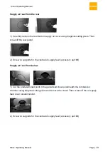
Page 18: ... off the rear panel 2 Screw on supports for the central air supply feed accessory part 6 Supply air feed from below 1 Cut the predetermined point in the galvanised sheet underneath the combustion chamber using diagonal cutting pliers and remove the sheet Then screw off the air supply feed cover located behind 2 Screw on supports for the central air supply feed accessory part 6 ...

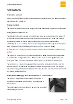
Page 19: ... footprint is higher PLEASE NOTE It is strictly necessary to observe the recommended fuel quantities and air settings The primary air entering the combustion chamber from below via the grate is responsible for performance as it generates most of the heat that leads to wood gasification This wood gas is burnt in a clean and efficient manner thanks to pre heated secondary air The secondary air comes...

Page 20: ...g to operate the device at nominal capacity Heat setting 2 A large amount of combustion air is needed in the igniting phase and the lever should be pushed all the way to the right to setting 2 maximum supply of primary and secondary air PLEASE NOTE Setting 2 should only be selected for igniting purposes Dampers left open Operation with the air control or appliance dampers open can cause excess smo...

Page 21: ...air in order to create an optimal combustion process low in emissions It flows right in front of the glass in the combustion chamber and is a key part of the combustion process at this location In doing so the glass is kept as clean as possible If despite this the glass becomes dirty this soot can be removed using glass cleaner which is specially designed for oven and stove glass when the device h...

Page 22: ...ically odourless and smoke free However if the device is heated before the varnish is completely dry it may result in an unpleasant yet harmless smoke or odour being produced for a short time Make sure that the room where the device has been installed is well ventilated Information on noises The device may emit clicking noises due to the heating and cooling processes These are caused by the enormo...

Page 23: ...le Then close the door to the combustion chamber You will start to see flames appear in the combustion chamber after just a short period 4 When all the pieces of wood are burning reduce the air supply by setting the regulator to Heating mode Move the air regulator above the combustion chamber from position II to position I 5 You should top the fire up when glowing embers remain and you can only se...

Page 24: ...all signs that the device is being misused Heating in the transitional period If outdoors temperatures are above 15 C there is the risk that the fire will only be moderate due to the chimney s low supply pressure This results in an increased build up of soot in the device flues and chimney Increase the supply of air stoke the fire more often and top up the fire with logs more often with smaller wo...

Page 25: ... compartment as well as the heating door so that they are completely open 90 You will find a catch located underneath the door closing mechanism This can be used to lock the door in place PLEASE NOTE Always keep the door to the combustion chamber closed when the device is in heating mode The door should only be fixed in place for cleaning purposes or to remove ash DANGER may arise if exhaust gases...

Page 26: ...mber Grate and ash holder PLEASE NOTE Do not empty the ash holder when it is hot Please note that seemingly cold ash may still contain small embers To avoid starting a fire it is recommended to place ash into a suitable metal container before throwing it away Wipe the ash into the ash holder through the slits of the grate using an ash slider Remove cinders encrustations and other deposits created ...

Page 27: ...nd 21 of the Clean Air Act 1993 by section 15 of the Deregulation Act 2015 Similarly in Scotland appliances are exempted by publication on a list by Scottish Ministers under section 50 of the Regulatory Reform Scotland Act 2014 In Wales and Northern Ireland these are authorised by regulations made by Welsh Ministers and by the Department of the Environment respectively Further information on the r...

Page 28: ...on on Heating correctly Operating temperature was not reached Use more fuel dry wood 20 residual moisture please pay attention to the air regulation Stove is not extracting properly Insufficient flue draught Clear with a chimney sweep possibly make the chimney longer measure the draught Stove has soot inside Use more fuel dry wood 20 residual moisture please pay attention to the air regulation See...

Page 29: ...rd Stuttgarter standard Munich The device was type tested at the RRF test centre in Drolshagen GER Test report number RRF 40 17 4786 SIRIUS 1 SIRIUS 3G Dimensions W x H x D 512 x 1218 x 392 mm 512 x 1218 x 392 mm Size of the combustion chamber W x H x D 360 x 349 x 277 mm 417 x 349 x 277 mm Diameter of the flue pipe outflow 150 mm 150 mm Diameter of fresh air connection 100 mm 100 mm Nominal heat ...

Page 30: ...Sirius Operating Manual Sirius Operating Manual Page 30 CE MARKING ...

Reviews: