13
ROUGH
CUT
MOWER
SERVICE
1. Raise deck to the highest cutting height and
remove top shields.
2. Remove drive shaft shield. Remove the front
u-joint from the drive shaft and slide it back.
3. Remove springs from the
A1
and
B1
spring
loaded idlers.
4. Remove the belt that drives the front spindles.
5. Remove the belt that drives the rear spindles.
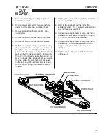
6. Refer to the illustration below and start installing
the rear spindle drive belt. Loop the belt around
the right rear spindle and place it in the bottom
groove of the triple groove pulley. Proceed to the
A3
fixed idler, then loop around the
A4
fixed idler.
Proceed to the left rear spindle, then around the
A1
spring loaded idler. Make a final loop around
the drive pulley. Be sure the belt is positioned
on the front side of the
A5
fixed idler as shown.
Do not connect spring until the second belt is
installed.
7. Replace the u-joint on the drive shaft and install
the drive shaft shield.
8. Refer to the illustration and install the front
spindle drive belt. This is a double sided belt and
does not have any twists in it.
9. Connect the spring to the
A1
spring loaded idler.
Choose a link that will stretch spring to a length
of 7-1/2 to 7-3/4 inches when installed.
10. Connect the spring to the
B1
spring loaded idler.
Choose a link and/or adjust eyebolt to stretch
spring to a length of 7-3/4 to 8 inches when
installed.
11. Replace top shields and adjust to the desired
cutting height.
Summary of Contents for 73-71010
Page 1: ...OP PARTS MANUAL MAN 4158503 Rev A 3 2007 MODEL 73 71010 ROUGH CUT MOWER RC466 ...
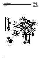
Page 16: ...14 ROUGH CUT MOWER MAIN FRAME FIGURE 1 ...
Page 18: ...16 ROUGH CUT MOWER PTO DRIVE SHAFTS FIGURE 2 ...
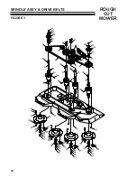
Page 20: ...18 ROUGH CUT MOWER SPINDLE ASSY DRIVE BELTS FIGURE 3 ...
Page 22: ...20 ROUGH CUT MOWER DECK ASSY SHIELDS FIGURE 4 ...


