background image

NOTICE !!!!  

Unauthorized modifications may present 

extreme  safety hazards to  operators and 

bystanders and  could also result in product 

damage.  

Schiller Grounds Care, Inc. strongly warns 

against,  rejects and disclaims any modifica-

tions, add-on  accessories or product altera-

tions that are not  designed, developed, tested 

and approved by  Schiller Grounds Care, Inc  

Engineering  Department. Any Schiller Grounds 

Care, Inc  product that is altered, modified or 

changed in any  manner not specifically  autho-

rized after original  manufacture-including the 

addition of “after-market” accessories by  Schil-

ler Grounds Care,  Inc.-will result in the Schiller 

Grounds Care, Inc.  

Warranty being voided.  

Any and all liability for personal injury and /or  

property  damage  caused by any unauthorized  

modifications, add-on accessories or products 

not  approved by Schiller Grounds Care, Inc.  

will be  considered the responsibility of the 

individual(s) or  company designing and/or 

making such changes.  Schiller Grounds Care, 

Inc. will vigorously pursue  full indemnification 

and costs from  any party  responsible for such 

unauthorized  post-manufacture modifications 

and/or accessories  should personal injury  

and/or property damage  result.   

This symbol means:  

ATTENTION !  

BECOME ALERT!  

Your safety and the safety of others is in-

volved.


Signal word definitions:  

The signal words below are used to identify levels of  

hazard seriousness. These words appear in this  manual 

and on the safety labels attached to Schiller  Grounds 

Care, Inc. machines. For your safety and  the safety of 

others, read and follow the information  given with these 

signal words and/or the symbols  shown above. Regard-

less of the hazard be  extremely careful.  

DANGER 

 Indicates an  imminently 

hazardous  situation which, if not avoided, 

WILL

 result in 

death  or serious injury.  

WARNING 

 Indicates a potentially 

hazardous  situation which, if not 

avoided, 

COULD

 result in  death or serious injury.  

CAUTION 

 Indicates a potentially haz-

ardous  situation which, if not avoided, 

MAY 

 result in minor  or moderate injury. It may  also  be 

used  to alert  against unsafe practices or property dam-

age.  

CAUTION 

 Used without the safety 

alert symbol  indicates a potentially 

hazardous situation which, if  not avoided, 

MAY 

result in 

property damage.   

3   

SAFETY   

Summary of Contents for 75-70666

Page 1: ...MODEL 75 70666 SNOWBLOWER 48 SB448 75 70667 SNOWBLOWER 54 SB454 Manual 4165 788 Rev A 9 2010 4165788_en K 09 ...

Page 2: ...2 ...

Page 3: ... in a safe and productive manner For longest life use this product only as directed in the manual keep it in good repair and follow safety warnings and instructions You ll always be glad you did NOTE All photographs and illustrations in the manual may not necessarily depict the actual models or attach ment but are intended for reference only and are based on the latest product information availabl...

Page 4: ...448 58 SB454 Overall Height 42 Overall Length 40 Opening Size 21 h x 48 w SB448 21 h x 58 w SB454 Auger 15 diameter open center Blower 14 diameter 4 blades Auger Speed 230 RPM Blower Speed 1150 RPM Chute 6 diameter 237 degree rotation Height of Cut Adjustable skid shoes 0 to 1 1 4 NOTE Specifications are subject to change without notice SERIAL NUMBER ___________________________ IF APPLICABLE MODEL...

Page 5: ...emnification and costs from any party responsible for such unauthorized post manufacture modifications and or accessories should personal injury and or property damage result This symbol means ATTENTION BECOME ALERT Your safety and the safety of others is in volved Signal word definitions The signal words below are used to identify levels of hazard seriousness These words appear in this manual and...

Page 6: ... before operating the vehicle and accessory This accessory is capable of amputating hands and feet and throwing objects Failure to observe the following safety instructions could result in serious injury All operators no matter how experienced they may be should read this and other manuals related to the vehicle and accessory before operating It is the owner s legal obligation to instruct all oper...

Page 7: ...n when using equipment on slopes Do not attempt to clear a steep slope 7 Never tolerate bystanders in the working zone Never use an accessory in the direction of by standers it might throw gravel or debris that can hurt people or damage property 8 Never operate the accessory at high transport speeds on slippery surfaces Use care when backing up 9 Do not carry passengers 10 Disengage power to the a...

Page 8: ...ile engine is running DECAL 105128 To avoid injury from drive belt Keep hands feet clothing away Do not attempt to install or remove drive belt without reading owner s manual DECAL 105130 Before installing or using Locate read and make sure to understand all of the owner s manual DECAL 105131 Refer to owner s manual about wearing safety glasses ear muffs and mask Re fer to owner s manual for use o...

Page 9: ...e the chute item 1 facing the rear and clip the back over the rotation ring then turn the chute towards the front to lock into place Sprocket installation 1 Turn the rotation sprocket item 10 and the chute item 11 in position as shown Make sure the sprocket stoppers item 12 and the rotation stop per item 13 are placed in the same position as shown 2 Install the four carriage bolts with four nylon ...

Page 10: ...he two bolts of the hydraulic motor support Guard installation 1 Install the chute rotation guards item 30 31 with the seven hex bolts 1 4 n c x x1 2 item 32 Drive belt installation 1 Remove the drive pulley shield item 40 and install the proper drive belt for the power unit Model 430 4165834 Model 235 4165850 2 Replace shield Extended wings with drift cutters installation For the SB454 model only...

Page 11: ... to the quick couplers on the tractor NOTE If the rotation does not match the lever operation the hoses may be reversed 7 Install the drive belt to the tractor See tractor s manual for belt tensioning specifications 8 A weight bar with four weights is required on 4 wheel drive units whenever the snowblower is installed Install according to weight bar instructions IF THE SNOWBLOWER STARTS WITHOUT E...

Page 12: ... in the highest position 2 Do the same tests as in snowblower installation sec tion item 9 If the snowblower starts and proper tension is used the pulleys are misaligned too much If at the highest position the two belts come into contact with each other There is not enough space between the pulleys STEP 4 SNOWBLOWER REMOVAL INSTRUCTIONS 1 Lower the snowblower and stop engine TO PREVENT INJURIES ST...

Page 13: ... switch for up or down deflector movement 11 When removing snow do not use the snowblower as a dozer blade to push snow Allow snowblower to ingest snow at its own speed If the speed of your tractor is too fast the snowblower may become over loaded and plug For best results raise the snowblower and remove a top layer of snow A second pass with the snowblower will remove the remaining snow CLEARING ...

Page 14: ...snowblower is in safe working condi tion Check chute rotation chain for excess slack Check skid shoe see installation section Check from to time the wearing on the cutting edge to make sure you do not wear out the base of the snow blower s chassis This cutting edge is reversible All you have to do is unscrew the bolts and turn the cut ting edge reinstall and tighten the bolts securely 50 Hours Che...

Page 15: ... of 10 for the fan The use of any other shear bolt will not insure any protection and may void the warranty IMPORTANT IT IS VERY IMPORTANT TO REPLACE THE AUGERS IN THE SAME POSITION AS SHOWN IN THE DRAWING BEFORE INSTALLING THE SHEAR BOLTS ONE SIDE AUGER SHOULD BE OPPO SITE OF THE OTHER SIDE END OF SEASON STORAGE Clean snowblower and subframe thoroughly and repaint all parts from which paint has w...

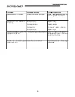
Page 16: ... see Maintenance section Installation Adjustment and Replacement section Snowblower belt has burn marks in specific places or the belt slips Lack of tension on belt Snowblower engaged when plugged Remove the bolt sleeve and the spring from the original hole item A and reinstall them in the lower hole item B Make sure the auger the fan are not frozen or plugged before engaging Chute plugs easily Tr...

Page 17: ...lley Damaged bearing Damaged fan Damaged auger Replace pulley Replace bearing Dismount repair or replace fan Replace auger Snowblower starts without the PTO engaged on model 430 Too much tension on the drive belt Lower the tension on the tractor s tensionner See tractor s manual for tensioning instructions Drive belt has burn marks in specific places or belt slips Lack of tension on the belt See t...

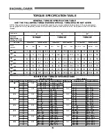
Page 18: ...8 3 4 19 05 150 185 203 3 250 7 270 324 366 1 439 3 380 456 515 3 618 3 7 8 22 23 160 200 216 8 271 400 480 542 4 650 9 600 720 813 6 976 3 1 25 4 250 300 338 8 406 5 580 696 786 5 943 8 900 1080 1220 4 1464 5 METRIC BOLT TORQUE SPECIFICATIONS COARSE THREAD FINE THREAD Size Screw Grade No Pitch mm Pounds Feet Newton Meters Pitch mm Pounds Feet Newton Meters M6 4T 1 00 3 6 5 8 4 9 7 9 7T 5 8 9 4 7 ...

Page 19: ...PARTS SECTION PARTS SECTION 17 ...

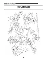
Page 20: ...PARTS BREAKDOWN SB448 SNOWBLOWER 18 ...

Page 21: ...Attaching plate 2 4165828 7 13 Sleeve 1 4165829 7 14 Guard 1 4165830 2 15 Support plate 1 4165831 7 16 Hose 76 2 4165832 17 Reinforcement plate 2 4165833 7 18 V belt MXV5 480 1 4165834 19 V belt MXV5 570 1 4165835 20 Chute 1 4165836 2 21 Chain guard 1 4165837 2 22 Chain guard 1 4165838 2 23 Rotation sprocket 1 4165839 24 Lift stopper 1 4165840 7 25 Protection plate 1 4165841 26 V pulley 1 4165813 ...

Page 22: ...65808 44 Key 1 4 x 1 4 x 2 1 64164 13 45 Flangette 2 4165795 46 Rotation bushing 4 4165805 47 Spring 1 4165800 48 Sleeve 1 4165801 49 Knob 2 4165792 50 Nylon flat washer 11 32 2 4165789 51 Nylon flat washer 7 16 2 4165790 52 Rotation ring 1 4165804 53 Key 1 4 x 1 4 x 1 3 4 3 64164 40 54 Flange washer 1 4165793 55 Quick nipple 1 4 ISO B 2 4165847 56 Reinforcement 1 4165811 7 57 Shear bolt N I L N f...

Page 23: ...bolt 5 16 n c x 1 6 O L 77 Carriage bolt 3 8 n c x 2 3 4 1 O L 78 Nylon insert lock nut 1 4 n c thin 6 O L 79 Nylon insert lock nut 1 4 n c 7 O L 80 Nylon insert lock nut 5 16 n c 17 O L 81 Nylon insert lock nut 3 8 n c 8 O L 82 Nylon insert lock nut 7 16 n c 6 O L 83 Nylon Insert lock Nut 1 2 n c 2 O L 84 Flange nut 1 4 n c 2 O L 85 Flange nut 5 16 n c 1 O L 86 Stover lock nut 5 16 n c 6 O L 87 F...

Page 24: ...PARTS BREAKDOWN SB454 SNOWBLOWER 22 ...

Page 25: ... 2 4165828 7 13 Sleeve 1 4165829 7 14 Guard 1 4165830 2 15 Support plate 1 4165831 7 16 Hose 76 2 4165832 17 Reinforcement plate 2 4165833 7 18 V belt MXV5 480 1 4165834 19 V belt MXV5 570 1 4165835 20 V belt MXV5 510 1 4165850 21 Chute 1 4165836 2 22 Chain guard 1 4165837 2 23 Chain guard 1 4165838 2 24 Rotation sprocket 1 4165839 25 Lift stopper 1 4165840 7 26 Protection plate 1 4165841 27 V pul...

Page 26: ...1 4 x 1 4 x 2 1 64164 13 46 Flangette 2 4165795 47 Rotation bushing 4 4165805 48 Spring 1 4165800 49 Sleeve 1 4165801 50 Knob 2 4165792 51 Nylon flat washer 11 32 2 4165789 52 Nylon flat washer 7 16 2 4165790 53 Rotation ring 1 4165804 54 Key 1 4 x 1 4 x 1 3 4 3 64164 40 55 Flange washer 1 4165793 56 Quick nipple 1 4 ISO B 2 4165847 57 Reinforcement 1 4165811 7 58 Shear bolt N I L N fan pkg 10 1 4...

Page 27: ... O L 79 Carriage bolt 5 16 n c x 1 6 O L 80 Carriage bolt 3 8 n c x 2 3 4 1 O L 81 Nylon insert lock nut 1 4 n c thin 6 O L 82 Nylon insert lock nut 1 4 n c 7 O L 83 Nylon insert lock nut 5 16 n c 17 O L 84 Nylon insert lock nut 3 8 n c 8 O L 85 Nylon insert lock nut 7 16 n c 6 O L 86 Nylon Insert lock Nut 1 2 n c 2 O L 87 Flange nut 1 4 n c 12 O L 88 Flange nut 5 16 n c 1 O L 89 Stover lock nut 5...

Page 28: ...now drift cutters Pkg of 2 OPTIONS ATTACHMENTS ELECTRIC DEFLECTOR KIT 970401 Allows to adjust the deflector electrically from driver s seat SNOW DRIFT CUTTER 970400 for Northeast snowblower Facilitates and increases snow intake Pkg of 2 26 ...

Reviews: