background image

64

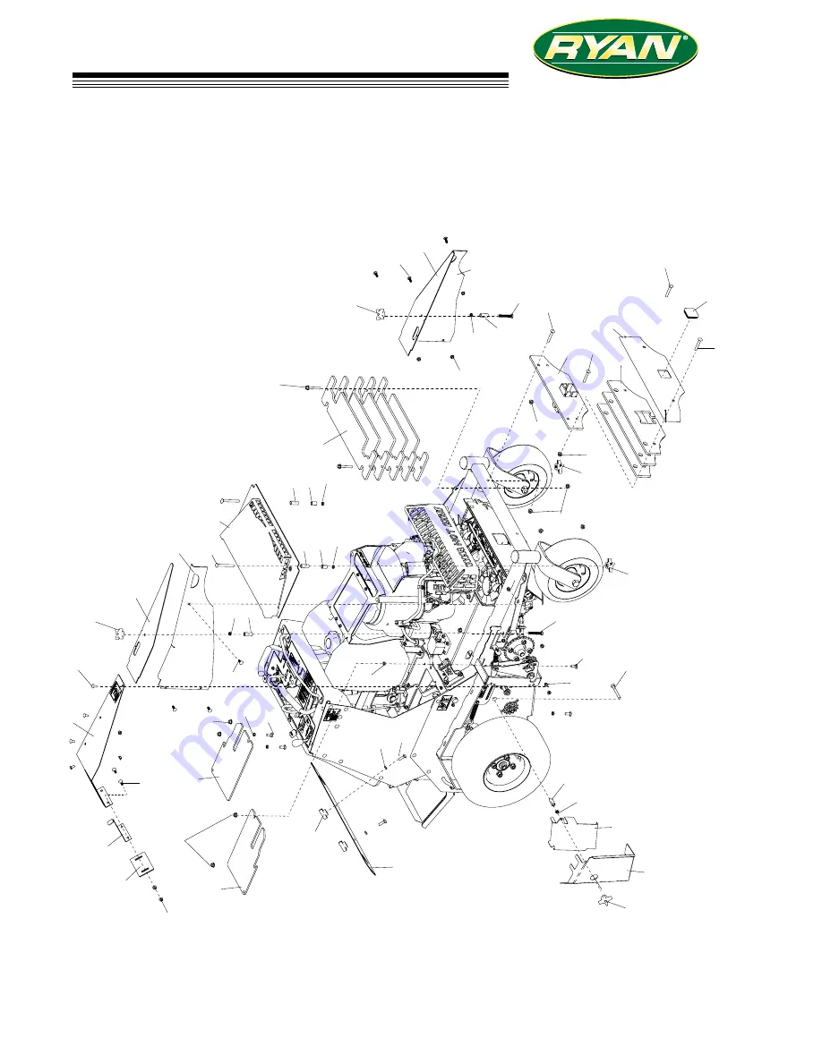
LAWNAIRE ZTS

64

FIGURE 15

COVERS & GUARDS

27

24

26

28

10

15

18

17

4

13

22

20

30

29

11

1

25

23

16

12

2

9

3

14

31

6

20

21

21

31

10

11

7

9

5

8

12

30

12

20

19

12

22

23

23 31

27

26

25

26

13

12

20

21

12

21

27

29

20

32

23

23

31 8

Summary of Contents for 0224

Page 1: ...PARTS OPERATORS S MANUAL MAN 4174368 Rev D 02 2019 554930A LAWNAIRE ZTS FS541V KAW S N 1575 and higher 554930ACA LAWNAIRE ZTS FS541V KAW S N 0224 and higher www ryanturf com ...

Page 2: ...equipped with a spark arrestor as defined in Section 4442 maintained in effective working order or the engine is con structed equipped and maintained for the prevention of fire To acquire a spark arrestor for your unit see your Engine Service Dealer Please refer to the engine manufacturer s information included with the machine Labeled power ratings are supplied by the engine manufacturer in accor...

Page 3: ...ine depends to a large extent on how well you read and understand these manuals Treat your machine properly lubricate and adjust it as instructed and it will give you many years of reliable service Your safe use of this Schiller Grounds Care Inc product is one of our prime design objectives Many safety features are built in but we also rely on your good sense and care to achieve accident free oper...

Page 4: ...ions and or accessories should personal injury and or property damage result This symbol means ATTENTION BECOME ALERT Your safety and the safety of others is involved Signal word definitions The signal words below are used to identify levels of hazard seriousness These words appear in this manual and on the safety labels attached to Schiller Grounds Care Inc machines For your safety and the safety...

Page 5: ...dicates that those operators age 60 years and above are involved in a large percentage of riding power related injuries Those operators should evaluate their ability to operate the riding machine safely enough to protect themselves and others from injury Do not carry passengers especially small chil dren They may fall off and be seriously injured Keep warning labels and this operator s manual legi...

Page 6: ...t machine and attachments if any are in good operating condition Do not lower tines until ready to aerate STARTING Start only according to instructions in this manual or on the machine Before attempting to start the engine make sure the parking brake is on the traction drive is in NEUTRAL When starting the engine make sure hands and feet are clear of the tines Do not change engine governor setting...

Page 7: ...ideways uphill to drive across the slope The machine turns downhill going across the slope You are uneasy about being on the slop With ride on machines including articulated steering machines operate up and down slopes not across except for zero turn machines Zero turn machines should operate across slopes With walk behind machines always operate across slopes not up and down Avoid starting or sto...

Page 8: ...a free of grass leaves debris buildup or grease Tines Tines are sharp and can cut Use extra caution when handling Wear appropriate personal protective equip ment WARNING FUEL Gasoline and diesel fuels are flammable gasoline vapors are explosive Use extra care when handling Store only in containers spe cifically designed for fuel When refueling or checking fuel level Stop the engine and allow to co...

Page 9: ... flame such as a water heater or an appliance with a pilot light Keep gasoline storage area free of grass leaves and excessive grease to reduce fire hazard Clean grass and debris from aerating units drives mufflers and engine to help prevent fires JUMP STARTING 1 Be sure the jumper cables are in good condition Turn off the ignition and all electrical accessories on both machines 2 Position the mac...

Page 10: ...io No lleve pasajeros Guarde a la gente lejos durante la operación ADVERTENCIA WARNING BEFORE STARTING OR SERVICING Read and understand the operator manual and all labels Be sure the machine is in safe operating condition and the operator presence works Make necessary repairs BEFORE LEAVING THE OPERATOR POSITION Apply parking brake Turn engine off Remove key AVOID SERIOUS INJURY OR DEATH Use cauti...

Page 11: ...green is white border ReadandunderstandtheOperatorManualbeforeservicing Every50hoursorweekly Yearly Checkhydrauliclevel Grease Checktirepressure Casterpivots 15psirear Transaxlepivot 25psifront Hydrauliccylinderpivot Checkchaintension Lubricatechain Fill with 20w50 motor oil to level indicated FULL COLD HYDRAULIC OIL WARNING STORED ENERGY TINES MAY DROP SUDDENLY SUPPORT LOWER TINES BEFORE SERVICIN...

Page 12: ...ched Move the lever rearward to decrease engine speed until the engine reaches its idle speed CHOKE C Pull the choke control out to set the choke ON Push it in to set the choke OFF PARKING BRAKE H Move the parking brake lever forward to latch it in the OFF position Move it sideways and to the rear to engage the parking brake The parking brake must be engaged to start the machine CONTROL LEVERS E1 ...

Page 13: ...line with the fuel line hose Close the valve by turning the knob a quarter turn to be perpendicular to the fuel line hose JACK STANDS L1 L2 Built in jack stands allow servicing the chains and the tine assembly without moving the machine To put the machine UP on the jacks lower the tines on a hard surface to raise the machine Pull the pin L2 on each jack L1 and drop it Put the pin back in the upper...

Page 14: ... BYPASS VALVES O Bypass valves allow the machine to be pushed or towed with the engine off and the parking brake disengaged A bypass valve for each transaxle is located under the weights at the front of the machine With the ma chine off and the parking brake disengaged pull the enlarged area of each valve rod through the guide hole in the frame and latch it to open the bypass valve Move the rod so...

Page 15: ...perated as a walk behind unit by raising the footplate and latching it in the stowed position Walk behind mode is useful when terrain or circumstances make operation as a ride on uncomfortable or even dangerous For example operation near a bank above a drop off or re taining wall would be places where walk behind mode should be used When operating as a walk behind operate across slopes not up and ...

Page 16: ...rmly until cap bottoms out on tube Dipstick assembly must always be secured into fill tube when engine is running ___ Check all lubrication points and grease as instructed in manual ___ Check hydrostatic fluid level Check to be sure cooling fins on hydrostat are clean ___ Perform a functional check of the safety interlock system each time you operate the unit PRE OPERATION CHECK LIST SERIOUS INJUR...

Page 17: ...tely do not crank for more than 10 seconds at a time Allow 60 seconds for the starter motor to cool down between starting attempts to prevent the starter motor from burning out 4 If the choke is ON when the engine starts gradu ally back it off until the engine runs with no choke at all DRIVING 1 Move the parking brake to OFF position 2 Move traction control lever out of neutral 3 Push both tractio...

Page 18: ...d farther forward from the neutral position Decrease speed when traveling forward pulling the traction levers rearward slows the machine Stopping The machine will stop when the levers reach the neutral position Reverse movement To move the machine straight back pull both traction levers back equally from their neutral position Re verse speed increases as the levers are moved back farther Maximum r...

Page 19: ...tines at the end of the pass turn around then lower the tines to continue on the next pass To finish aerate the perimeter Use of the Depth Stops J1 J2 The depth stops enable consistent core depth in varying soil conditions by setting the maximum core depth A consistent core depth keeps the machine from bogging down when going from harder to softer soil for more consistent operation and better perf...

Page 20: ...uel do not store equipment with fuel in tank or carburetor in an enclosure with an open flame for example a furnace or water heater pilot light Before the equipment is put into storage for any period exceeding 30 days the following steps should be taken 1 Drain all fuel from the fuel tank and fuel lines 2 Start the engine and run until all the fuel is used from the carburetor float bowl 3 While th...

Page 21: ...be kept inflated at 15 lbs in2 1 05kg cm2 Improper tire inflation can cause rapid tire wear and poor traction Uneven inflation can cause uneven aerating Front tires should be 25 lbs in2 1 75 kg cm Engine Maintenance Air Filter Maintain the air filter according to the manufacturer s engine owners manual Engine Oil Check engine oil level daily Top off if necessary See engine owners manual BATTERY AG...

Page 22: ...ise machine 1 Start the engine 2 Pull depth stop pins 3 Lower the tines on a hard surface 4 Increase tine pressure to raise the machine 5 Pull jack stand pins and pin in raised position 6 Raise tines to set machine on stands NOTE Machine may be dropped gently onto the jack stands by reducing the tine down force until the machine lowers Then raise tines to the transport position Lower machine 1 Sta...

Page 23: ... 1 Check oil level with the dipstick 2 If oil is needed add fresh oil of proper viscosity and grade See engine manual for oil specifications Do not overfill 3 Replace dipstick before starting engine PERIODIC OIL CHANGES 1 See engine manual for oil and filter change inter vals after the break in period 2 Follow instructions for first oil change above SPARK PLUGS Remove each plug and check condition...

Page 24: ...he corresponding drive and apply lubricant to each side of the chain until the entire chain is lubricated Take care not to get caught in tines 5 Repeat for the other tine chain 6 Check tension for adjustment Some slack is normal See adjustment section if adjustment is needed 7 Flip the chain cover doors down Reinstall the rear cover 9 Lower the machine Stop the engine and pin the jack stands in th...

Page 25: ...r drain plug and reinstall in the reservoir Oil the gaskets of the new transaxle hydraulic oil filters and install on the transaxles Tighten 3 4 to 1 turn past the point where the gasket contacts the mount ing surface Reinstall the filter covers Oil the gasket on ta new lift circuit filter and install on the filter head Tighten 3 4 to 1 turn past the point where the gasket contacts the filter head...

Page 26: ...op 4 With the bypass valve closed and the engine running slowly move the control levers in both forward and reverse directions 5 to 6 times 5 Stop engine Check the transaxle fluid level add fluid as required 6 It may be necessary to repeat steps 3 5 until all the air is completely purged from the system When the transaxle moves forward and reverse at normal speed purging is complete 7 Lower the ma...

Page 27: ...ne can cause water to enter bearings and other components This can greatly reduce component life DO NOT use a pressure washer Do not direct water at bearings or seals High pressure water can blow past seals and enter sealed bearings Allow the machine to cool down before washing Water on a warm machine can be sucked into sealed bearings as they cool Avoid getting electrical connections wet Water ca...

Page 28: ...s n o C p U p o T k c e h C l e v e L l i O X s k a e L r o F k c e h C X e k a t n I r i A n a e l C n e e r c S X r e n a e l C r i A n a e l C r e n a e l c e r P X r e n a e l C r i A n a e l C t n e m e l E X s n i F g n i l o o C n a e l C X d n A l i O e g n a h C r e t l i F al u n a m s r e r u t c a f u n a m e n i g n e e e S e c a l p e R k c e h C s g u l P k r a p S X E L X A S N A R...

Page 29: ...ening the jam nuts against the bracket Install the bracket loosely to the frame Pull the cable conduit until the barrel fitting just touches the bracket on the brake lever PARKING BRAKE SWITCH The parking brake switch needs to be adjusted so the plunger is depressed when the parking brake is OFF Figure 3 1 Move the parking brake to the OFF position 2 Loosen the parking brake switch mounting screws...

Page 30: ...e location of the traction lever in the slot by way of adjustment can be used to affect top forward speed and reverse speed of the unit within the limits of the transaxles control stroke Adjusting the LH control to the rear of the neutral slot will increase forward speed by reducing the available stroke for reverse and lowering maximum reverse speed Do not adjust beyond the point where the end of ...

Page 31: ...gine and pin the jack stands in the operat ing position MAIN DRIVE CHAIN ADJUSTMENT The main drive chain has an automatic tensioning system that normally does not require adjustment As the chain wears the tensioner advances and locks the idler in the new position If the automatic tension has advanced all the way it may be reset 1 Raise the machine and support it on the built in jack stands Turn of...

Page 32: ...the remaining pulleys 3 Loop a new belt around the transaxle and engine pulleys Rotate the idler arm in a counter clockwise direction to enable the new belt to be installed in the idler pulley 4 Reinstall the engine transaxle belt 5 Reinstall the front cover ENGINE HYDRAULIC PUMP BELT 1 Remove the front cover The two knobs which secure it are located on the underside of the machine 2 Remove the en...

Page 33: ...n with a new connector link NOTE Install all con nector links so the closed end is in the direction of forward travel 5 Push the idler up to take all the slack out of the new chain and tighten the idler bolt Make sure the slack is out of the top span of the chain Move the tensioner off the locking notch to en gage the locking teeth 6 Reinstall the chain covers Start the engine and lower the machin...

Page 34: ...any sprockets are worn remove the chain and replace sprockets If the sprockets are still in good condition connect the new chain to the old chain and use the old chain to pull the new chain around the sprockets Remove the old chain and connect the ends of the new chain with a new connector link NOTE Install all connector links so the closed end is in the direction of forward travel 7 Set the axle ...

Page 35: ... type in transaxle TRANSMISSION DRIVE SYSTEM Belt from engine to hydrostat input shafts hydrostatic drive to wheels and tines via 50 chain TURNING RADIUS True zero tines up Approximately 48 radius tines down HYDRAULIC RESERVOIR CAPACITY Reservoir 2 75 quarts Transaxles 2 quarts Total Capacity 6 75 quarts POWER STEERING Independently controlled drive wheels WEIGHT 554930 Dry Approximately 1210 lbs ...

Page 36: ...to engine manufacturer s speci fications and website OUTPUT TORQUE 31 0 ft lb 42 1 Nm 2200 rpm OIL CAPACITY 1 8 qt 1 7L LUBRICATION Full Pressure CYLINDER BLOCK Aluminum with cast iron sleeve CYLINDER HEAD Aluminum GOVERNOR Mechanical AIR CLEANER Dual Element IGNITION SYSTEM Electronic CHARGING SYSTEM 12V 15AMP BATTERY 12V FUEL CAPACITY 5 0 GAL 18 9 L FUEL TANK Polyethylene FUEL CONSUMP TION MAX L...

Page 37: ...35 LAWNAIRE ZTS PARTS SECTION PARTS SECTION ...

Page 38: ...36 LAWNAIRE ZTS FIGURE 1 UPPER ENGINE ASSEMBLY 3 25 27 29 19 16 18 15 17 2 24 4 23 22 20 5 11 13 12 14 6 8 10 9 21 7 1 26 28 16 25 27 8 4 6 26 27 25 ...

Page 39: ... 1 11 64229 01 NUT NYLON LOCK 1 4 20 4 12 4172735 7 BRKT OIL COOLER 1 13 2188173 COOLER OIL 1 14 2720891 7 SCREEN OIL COOLER 1 15 4164252 001 FITTING 3 8NPT TO 3 8 BARB 1 16 88042 03 CLAMP HOSE 5 8 2 17 69053 05 HOSE HYDRAULIC 14 1 18 48412 01 CLIP CABLE 3 4 J X 10 32 1 19 4164251 DRAIN VALVE 1 20 4164359 MUFFLER FS600 KAW 1 21 4164382 ENG 18HP KAW FS541V ES 1 22 64163 69 WSHR 391X 88X10 GA 2 23 6...

Page 40: ...38 LAWNAIRE ZTS FIGURE 2 LOWER ENGINE ASSEMBLY 5 36 2 9 1 39 13 14 26 25 16 21 20 17 18 19 34 15 23 27 24 33 12 28 30 8 32 11 3 37 29 31 35 4 6 28 10 7 18 19 22 41 23 40 38 23 ...

Page 41: ...9 29 17 85010N ZERK 1 4 28 STR SELF THRD 1 18 4128004 BEARING BALL 10 X 26 X 8 3 19 64144 40 SNAP RING 26MM INTERNAL 2 20 548138 BRG NDL 88 1 12 1 00 1 21 521438 GREASE SEAL 1 22 64123 87 BLT HEX 3 8 16 X 1 3 4 1 23 64229 03 NUT NYLON LOCK 3 8 16 3 24 33148 01 SPACER 0 379X0 750X0 25 1 25 4171403 PIN SPRING 1 26 4171399 PIN MNTING PUMP IDLER 1 27 64123 217 BLT HEX 3 8 16X4 1 4 1 28 64006 03 LOCKWS...

Page 42: ...2 31 38 35 30 5 3 4 1 20 8 7 17 2 24 18 14 25 15 11 36 7 28 10 16 6 12 23 13 29 31 27 8 12 9 9 36 26 30 30 30 13 30 22 21 26 19 31 31 8 10 9 9 8 21 5 13 13 11 41 5 42 40 41 USED ON 554930 ONLY USED ON 554930CA ONLY To Rollover Vent on Tank To Carburetor To Carburetor ...

Page 43: ... BATTERY 190CCA 1 20 2228065 DAMPER NON CAVITATING 2 21 2000590 LABEL WARN BATTERY 1 22 4172659 7 WLDMT BATTERY SUPPORT 1 23 4172910 LABEL RESERVOIR 1 24 4171281 CYLINDER 2 25 X 3 0 1 25 4171592 PIN CYLINDER 1 26 64018 51 BLT CRG 5 16 18 X 3 4 SN 6 27 64268 03 NUT FL NYLON LOCK 3 8 16 4 28 64018 44 BLT CRG 3 8 16X1 SN 4 29 85010N ZERK 1 4 28 STR STH 1 30 64268 02 NUT FL NYLON LOCK 5 16 18 10 31 54...

Page 44: ...42 LAWNAIRE ZTS FIGURE 4 WHEEL ASSEMBLIES 21 2 26 24 23 22 9 25 1 6 7 8 20 5 12 11 13 16 15 17 19 18 3 4 10 14 26 27 27 29 28 31 ...

Page 45: ...13 4167554 01 BEARING SPINDLE SEALED 4 14 4172715 SPACER SPINDLE 2 15 4171467 7 WLDMT WHEEL HUB 2 16 85010N ZERK 1 4 28 STR SLF THRD 2 17 48480 SEAL CR 12411 2 18 64284 16 NUT FL CRLK 5 8 18 2 19 64209 03 SPRING WASHER 67 ID 2 20 64164 12 KEY 1 4X1 SQ 2 21 64001 6 NUT HEX JAM 3 8 16 8 22 64163 26 WSHR 766 ID X 1 625 2 23 64025 20 NUT HEX 3 4 16 SLOT U 2 24 64140 9 COTTER PIN 1 4 2 2 25 4162986 CAP...

Page 46: ...44 LAWNAIRE ZTS FIGURE 5 PARKING BRAKE ASSY 1 2 3 4 6 7 8 9 10 11 12 13 14 15 16 17 18 19 20 21 21 23 24 25 26 28 27 23 22 31 30 29 31 30 34 5 32 ...

Page 47: ...5 64018 47 BLT CRG 3 8 16X2 3 4 1 16 64262 018 BLT FLG HD 3 8 16 X 1 3 4 1 17 64141 4 NUT WLF 3 8 16 4 18 64152 46 SCREW SLT HH 10 24X1 2 2 19 4113682 ROD SPRING MOUNT 2 20 64018 51 BLT CRG 5 16 18 X 3 4 SN 1 21 64229 03 NUT NYLON LOCK 3 8 16 2 22 64163 55 WSHR 328X 75X14 GA 2 23 64168 2 COTTER HAIRPIN 08 X 1 19 3 24 64163 31 WSHR 25 64X1X12 1 25 64025 15 NUT HEX 10 24 KEPS 2 26 64018 7 BLT CRG 3 ...

Page 48: ... R R R R B B B B B B B B O O O O O O O O OB OB Y Y YB YB YR YR W WB W W W W G G B B B W WB P WIRE COLORS AND GAUGE CODE COLOR GAUGE UNLESS NOTED B BLACK 16 G GREEN 16 O ORANGE 16 OB ORANGE W BLACK STRIPE 16 P PURPLE 14 R RED 14 W WHITE 16 WB WHITE W BLACK STRIPE 16 Y YELLOW 16 YB YELLOW W BLACK STRIPE 16 YR YELLOW W RED STRIPE 16 14 GA B B B 8 0 EXP 6 7 5 3 9 2 3 4 1 2 SOLENOID 4 TO SOLENOID 2 RED...

Page 49: ...1 5 108208 SWITCH DBL POLE 1 6 4177930 METER HOUR 1 7 2308094 SWITCH NCNC 1 8 4171893 SWITCH ROCKER 1 9 148082 20 FUSE 20 AMP 2 10 4171099 BATTERY AGM TYPE 1 4171973 CHARGER AGM 11 2722227 05 CABLE BATTERY 18 COND 1 INCLUDES ITEM 14 15 12 108061 17 CABLE BATTERY 16 RED 1 13 108061 16 CABLE BATTERY 31 5 BLK 1 14 2308095 COVER TERMINAL 3 15 112386 BOOT BAT TERM POS 1 FIGURE 6 ELECTRICAL SYSTEM ...

Page 50: ...48 LAWNAIRE ZTS FIGURE 7 TRANSAXLE ASSEMBLY 20 33 6 7 4 2 26 31 32 1 18 10 31 12 13 25 14 5 17 21 23 30 19 27 8 11 5 5 29 28 24 22 16 15 9 3 5 11 TO OIL COOLER FROM RESERVIOR 25 24 ...

Page 51: ...16 18X2 3 4 4 14 64163 02 WSHR 321 328X 593 608X11GA 4 15 4174270 TUBE TRANS COOLER 1 16 G8062 CLAMP HALF 3 8 INSULATED 3 17 2720977 SPRING COMPRESSION 2 18 4173649 SPROCKET W SPACER 28T 2 19 64229 01 NUT NYLON LOCK 1 4 20 2 20 4171666 7 PLT DUMP VALVE 1 21 64168 2 COTTER HAIRPIN 08 X 1 19 2 22 4171606 CLAMP HALF 5 8 HOSE 4 23 64262 008 BLT FLG HD 5 16 18 X 1 2 24 64141 2 NUT WLF 1 4 20 7 25 64139...

Page 52: ...STEM 19 1 2 3 4 38 39 37 36 24 25 26 5 23 33 23 29 41 30 22 29 6 5 20 6 21 13 22 35 2 63 15 35 5 75 22 35 9 625 18 14 28 28 31 32 20 32 20 18 7 8 32 7 75 10 9 28 34 32 17 5 33 16 28 12 22 27 3 25 31 28 17 11 11 31 27 11 25 22 28 41 28 28 40 ...

Page 53: ... 2690030 01 FITTING 9 16 18 ORB X 3 8 2 19 4166840 03 HOSE 6 JIC 90 JIC X 39 75 1 20 2690030 03 FTG 3 4 16 ORB X 1 2 BARB 1 21 25 2503 8 6 FITTING 90 9 MORB X 6 MJIC 1 22 88042 04 CLAMP HOSE 9 23 27 017 01 HOSE HYD 42 L 2 24 4166839 03 HOSE 6 JIC JIC 19 5 1 25 4166839 02 HOSE 6 JIC JIC 18 5 1 26 25 2503 6 6 FITTING 90 6 MORB X 6 MJIC 2 27 108044 01 HOSE HYDRAULIC 11 25 2 28 88042 05 CLAMP HOSE 13 ...

Page 54: ...IRE ZTS FIGURE 9 CONTROL PANEL TOWER ASSY 4 23 25 17 16 14 15 13 20 26 1 22 21 12 7 8 9 10 27 2 5 19 3 18 11 24 6 7 24 14 14 11 14 11 33 32 31 11 30 23 35 34 29 28 11 5 TO RESERVOIR TANK TO CYLINDER TO PUMP 22 ...

Page 55: ... 17 15 25 2503 4 4 FITTING 90 4MORB x 4 MJIC 1 16 4171511 BAR REFERENCE REVERSE 2 17 108009 03 CONTROL CHOKE 51 1 18 64025 04 NUT 3 8 24 HEX 1 19 4170593 7 WLDMT FRONT POINT 1 20 64152 46 SCREW SLT HH 10 24X1 2 2 21 64025 15 NUT HEX 10 24 KEPS 2 22 48228 2A CLAMP 3 4 CLIP 2 23 64018 2 BLT CRG 1 4 20X3 4 3 24 4171606 1 CLAMP HALF 5 8 HOSE 2 25 64262 005 BLT FLG 1 4 20 X 1 1 2 3 26 25 0503 6 6 FITTI...

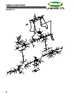
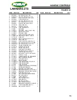
Page 56: ...2 26 28 38 5 44 49 48 50 42 37 10 8 12 9 3 42 15 18 14 17 4 13 53 22 20 7 19 11 36 33 6 32 35 23 30 29 39 42 1 45 34 25 21 41 31 47 11 6 1 28 45 42 22 20 23 43 43 22 28 28 28 46 20 35 33 22 36 23 16 23 13 16 24 10 2 4 53 12 2 9 3 17 7 6 20 37 51 51 51 51 ...

Page 57: ...608X11GA 4 24 4171433 7 WLDMT LIFT PIVOT 1 25 64163 31 WSHR 25 64X1X12 1 26 64025 15 NUT HEX 10 24 KEPS 2 27 64152 49 SCREW SLT HH 10 24X1 25 2 28 64229 03 NUT NYLON LOCK 3 8 16 11 29 64158 01 EYE BOLT 10 24 X 1 25 THD LG 1 30 64141 15 NUT WLF 10 24 2 31 4171442 HANDLE CNTRL OP PRESENCE 1 32 4171515 7 BRKT CONTROL LEVER 1 33 64025 03 NUT HEX 5 16 24 2 34 4171520 7 BAR CONTROL 1 35 4143595 02 ROD E...

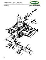
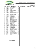
Page 58: ...56 LAWNAIRE ZTS FIGURE 11 DEPTH STOP HOC ASSEMBLY 17 36 9 37 24 22 25 19 27 30 35 21 4 11 28 34 32 2 3 31 1 5 33 18 16 6 6 15 20 23 26 29 12 26 14 15 2 13 13 7 8 38 10 7 38 22 20 32 37 ...

Page 59: ... 16 4 16 64163 74 WASHER 516 X 2 00 X 250 2 17 64018 13 BLT CRG 1 2 13X2 GR5 2 18 64268 05 NUT FL NYLON LOCK 1 2 13 2 19 4168176 TUBE PIVOT IDLER INNER 2 20 64163 19 WSHR 33 64X1 1 4X12GA 4 21 64123 72 BLT HEX 1 2 13X2 1 2 2 22 64141 13 NUT WLF 1 2 13 4 23 4176686 7 WLDMT IDLER ARM 2 24 64197 022 BLT TDFM 3 8 16X3 4 4 25 4166324 03 BEARING PLASTIC 1 000 ID 2 26 64163 36 WSHR 1X33 64X 187 4 27 6412...

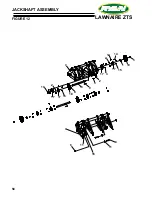
Page 60: ...58 LAWNAIRE ZTS FIGURE 12 JACKSHAFT ASSEMBLY 13 2 7 4 16 6 1 5 11 10 18 19 3 12 15 14 17 2 17 17 17 2 15 3 9 7 8 11 ...

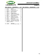
Page 61: ...F 1 2 13 2 7 4177234 7 WLDMT TINE ASSY 1 8 64044 18 SCREW SET 5 16 18 x 5 16 4 9 64164 28 KEY 1 4 X 1 15 WOODRUFF 2 10 64221 1 E RING 25MM 1 00 2 11 64163 124 WSHR 531 X 1 50X 1 25 6 12 64044 13 SCREW SET 1 4 28X1 4 16 13 4174131 SHAFT HALF TINE DRIVE 2 14 64164 12 KEY 1 4X1 SQ 2 15 64018 51 BLT CRG 5 16 18 X 3 4 SN 8 16 83 5013E08 SPROCKET WHEEL FRONT 2 17 4168069 BEARING 1 FLUSHMOUNT 8 INCLUDES ...

Page 62: ...60 LAWNAIRE ZTS FIGURE 13 TINE ASSEMBLY 1 2 3 4 5 9 10 12 18 14 8 17 16 19 15 12 13 11 9 10 4 3 3 4 6 5 6 ...

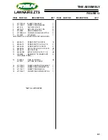
Page 63: ...S ALL 6 CHAINS FOR UNIT AND LINKS 8 64044 13 SCREW SET 1 4 28X1 4 12 9 64044 18 SCREW SET 5 16 18 x 5 16 2 10 64044 25 SCREW SET 5 16 18X1 2 2 11 64268 02 NUT FL NYLON LOCK 5 16 18 48 12 64164 12 KEY 1 4X1 SQ 2 13 64262 008 BLT FLG HD 5 16 18 X 1 1 4 48 14 4168069 BEARING 1 FLUSHMOUNT 6 INCLUDES ITEM 8 15 C100032 TINE PLUGGING 48 4173511 KIT TINE 48 COUNT 16 4171338 7 WLDMT CENTER TINE SHAFT 1 17 ...

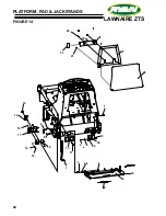
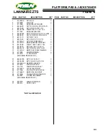
Page 64: ...62 LAWNAIRE ZTS FIGURE 14 PLATFORM PAD JACKSTANDS 31 29 30 20 21 27 3 28 6 8 7 22 19 23 24 9 11 13 18 15 14 12 2 17 26 1 25 4 5 10 16 ...

Page 65: ...7 PLT PLATFORM BRKT 2 13 4172318 7 BRKT BUMPER SUPPORT 2 14 64163 86 WSHR 265 X 625 X 125 4 15 64189 16 BLT HEX SOC 1 4 20 X 1 4 16 64229 01 NUT NYLON LOCK 1 4 20 4 17 4172315 7 BRKT PLATFORM DAMPER 2 18 4170585 BUMPER RADIAL 4 19 4173514 S PLATFORM 1 INCLUDES ITEMS 22 23 20 64262 003 BLT FLG 1 4 20 X 1 2 21 64262 002 BLT FLG HD 1 4 20 X 3 4 4 22 4166324 06 BEARING SLEEVE 2 23 4170670 MAT FOOTPLAT...

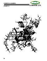
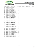
Page 66: ... ZTS 64 FIGURE 15 COVERS GUARDS 27 24 26 28 10 15 18 17 4 13 22 20 30 29 11 1 25 23 16 12 2 9 3 14 31 6 20 21 21 31 10 11 7 9 5 8 12 30 12 20 19 12 22 23 23 31 27 26 25 26 13 12 20 21 12 21 27 29 20 32 23 23 31 8 ...

Page 67: ...4173509 S FENDER LEFT 1 15 4176083 7 PLT PIN LOCK RIGHT 1 4176139 7 PLT PIN LOCK LEFT 1 16 4171489 7 PLT TIRE SCRAPER 2 17 4172852 2 PLT TINE COVER REAR 1 18 4176578 7 COVER CHAIN RH 1 4176577 7 COVER CHAIN LH 1 19 4172229 7 COVER CHAIN RH REAR 1 4172228 7 COVER CHAIN LH REAR 1 20 64268 03 NUT FL NYLON LOCK 3 8 16 10 21 64018 31 BLT CRG 3 8 16 X 2 1 2 4 22 64018 47 BLT CRG 3 8 16X2 3 4 2 23 64229 ...

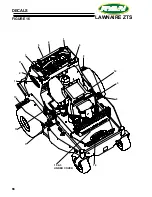
Page 68: ...66 LAWNAIRE ZTS FIGURE 16 DECALS 1 2 3 3 4 5 8 7 6 9 10 12 11 13 14 14 15 3 UNDER COVER ...

Page 69: ...SERVOIR 1 6 4172877 LABEL LAWNAIRE ZTS 1 7 4161125 LABEL RYAN OVAL 3 5 1 8 4172912 LABEL HYDRA COOL 1 9 4172915 LABEL JACKSTAND 1 10 4172911 LABEL SLOPES CA SPARK 1 11 4172914 LABEL TINES 1 12 4172886 LABEL DEPTH CONTROL LH 1 13 4172887 LABEL DEPTH CONTROL RH 1 14 4161123 LABEL RYAN OVAL 10 4 15 4172916 LABEL BELT ROUTING 1 16 2000735 LABEL OP MANUAL 1 LOCATED ON DOCUMENT TUBE 17 4176056 LABEL TEX...

Page 70: ...SCHILLER GROUNDS CARE INC ONE BOB CAT LANE P O BOX 469 JOHNSON CREEK WI 53038 920 699 2000 www schillergc com Schiller Grounds Care Inc 2010 ...

Reviews: