background image

7

CHIPPER/

SHREDDER

INSTALLATION

MOUNTING INSTRUCTIONS

The chipper/shredder should be used only on the Steiner 420, 425 and 525 power units equipped

with the required chipper/shredder electrical outlet.  (This electrical outlet is shipped with each chipper/

shredder.  See Page 27 for electrical outlet installation.)

NOTE: 

 The PTO drive line is subject to shock loads while using the chipper/shredder.  Therefore, the

chipper/shredder is not recommended for use on the Steiner 220 power unit.  Damage to the hydrostatic

pump may result.

To mount the Chipper/Shredder do the following steps:

1.  Open quick hitch latches.  Drive tractor into position, aligning the quick hitch.  Be sure that both latches 

are fully engaged and locked.

2.  Stop engine!  Do not attempt to install drive belt with engine running.

3.  Release double idler assembly to facilitate easy installation of the B-41 drive belt.  Put belt over drive 

pulley and engage or adjust double idler assembly.  (See Power Unit Operator’s Manual for PTO belt 

tension adjustment.)

4.  Plug emergency stop cable into chipper/shredder electrical outlet on tractor.  Be certain the Emergency 

Stop Switch is pulled out for normal operation.  Do not operate the Chipper/Shredder without this cable 

plugged in.

5.  Remove clip pin and rotate stand to highest position.  Reinsert clip pin.

6.  A rear weight bar with 4 weights is recommended to provide additional stability in transport.

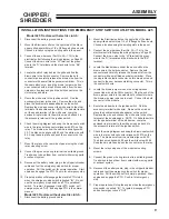
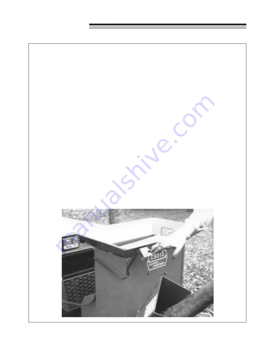
7.  Start engine, engage PTO and check operation of Emergency Stop Switch. (See photo below)

Summary of Contents for 73-70900

Page 1: ...OP PARTS MANUAL MAN 4158496 Rev A 3 2007 MODELS 73 70900 CHIPPER SHREDDER CS312 75 70902 CHIPPER SHREDDER BLOWER ATTACHMENT CS3130 ...

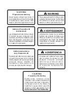
Page 2: ...tado de California hace saber que los gases de escape de los motores diesel y algunos de sus componentes producen cáncer defectos de nacimiento y otros daños en el proceso de reproducción humana L émission du moteur de ce matériel contient des produits chimiques que l Etat de Californie considère être cancérigènes provoquer des défauts congénitaux et d autres dangers en matière de reproduction El ...

Page 3: ...ts possible from Schiller Grounds Care Inc products You can trust Schiller Grounds Care Inc replacement parts because they are manufactured with the same high precision and quality as the original parts Schiller Grounds Care Inc designs and builds its equipment to serve many years in a safe and productive man ner For longest life use this product only as directed in the manual keep it in good repa...

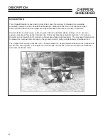
Page 4: ... cornstalks plants prunings vines etc can easily be processed through the shredder inlet Sticks and branches should be limited to 1 1 2 inches in diameter and no longer than 24 inches to avoid excess whipping and wrapping The processed material can be placed in a compost pile or spread on the ground as mulch giving a professionally landscaped look The chipper inlet can chip branches up to 4 inches...

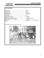
Page 5: ...72 Hardened Rotor Diameter 18 Rotor Width 12 Rotor Speed maximum 1550 RPM Shredder Throat Opening 9 1 2 X 11 Maximum material size for Shredder 1 1 2 diameter X 24 long Maximum material size for Chipper 4 diameter Application Steiner 420 425 525 Power Units Only Weight 430 lbs Specifications are subject to change without notice SPECIFICATIONS ...

Page 6: ...st manufacture modifications and or accessories should personal injury and or property damage result This symbol means ATTENTION BECOME ALERT Your safety and the safety of others is involved Signal word definitions The signal words below are used to identify levels of hazard seriousness These words appear in this manual and on the safety labels attached to Schiller Grounds Care Inc machines For yo...

Page 7: ...ate this machine 6 Keep people and pets a safe distance away from machine using power driven attachments Injury could result from flying debris GENERAL SAFETY OPERATING SAFETY 1 STOP ENGINE to install drive belt 2 DO NOT attempt to work on unit or any attachments with the engine running STOP ENGINE 3 Before leaving the operator s seat Disengage PTO drive Set Parking brake Stop Engine ALWAYS WEAR S...

Page 8: ...ate machine on a paved concrete or hard gravel surface Discharged material may rebound 6 Emergency stop switch must have cable plugged into outlet on power unit Do not operate machine without this emergency stop switch connected 7 When feeding shreddable material into the machine be extremely careful that pieces of metal rocks bottles cans or other foreign objects are not fed into the feeding cham...

Page 9: ...g the quick hitch Be sure that both latches are fully engaged and locked 2 Stop engine Do not attempt to install drive belt with engine running 3 Release double idler assembly to facilitate easy installation of the B 41 drive belt Put belt over drive pulley and engage or adjust double idler assembly See Power Unit Operator s Manual for PTO belt tension adjustment 4 Plug emergency stop cable into c...

Page 10: ...ay bulk connector where the brown wire was removed in step 3 Connect the bulk connector to the safety relay 6 Route the white wire to the ignition switch Find the accessory terminal white wire Remove the wire and place the double male spade adapter on the switch Replace the wire and connect the white wire to the other terminal of the double spade NOTE On Kubota tractors cut the spade terminal off ...

Page 11: ...itch pull emergency knob OUT and engage PTO in the normal manner Model 425 Tractors without electric clutch 1 Disconnect the battery ground cable INSTALLATION INSTRUCTIONS FOR EMERGENCY STOP SWITCH OUTLET ON MODEL 425 2 Mount the Electrical outlet on the right side of the black upper grille panel with two 1 4 x 3 4 flange bolts and nuts Choose a location using the existing slots in the panel 3 Con...

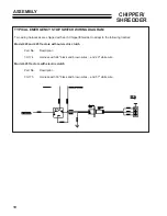
Page 12: ...each Chipper Shredder to adapt to the following tractors Model 420 and 425 Tractors without electric clutch Part No Description 30 174 Harness with 44 black and brown wires and 20 white wire Model 425 Tractors with electric clutch Part No Description 30 175 Harness with 33 black and brown wires and 57 white wire ...

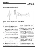
Page 13: ... connector of the blue wire that goes to the front lift limit switch 6 Route the blue wire from the new harness to the Diagram No 2 for Model 525 Tractors w o 2 Second Delay before serial no 1197 PTO switch Find the PTO switch terminal with the blue wire attached Remove the wire and place the double male spade adapter on the switch Replace the wire and connect the new blue wire to the other termin...

Page 14: ...lay Either gray wire can be used 8 Install the other gray wire from the new harness 30 301 into the new relay plug so that it will connect with the 30 terminal of the new relay 9 Install the supplied black wire approx 11 long to the new relay plug so that it will connect with the 85 terminal of the new relay Install the eyelet end to the ground bolt on the dash Also install the black wire from the...

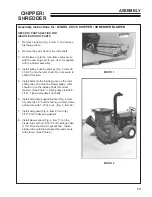
Page 15: ...t secure to shaft at this time 5 Install belt onto the inside groove on the rotor shaft pulley and onto the blower pulley Idler should run on the inside of belt for correct tension See Photo 1 Align pulleys to within 1 16 Tighten all pulleys on shafts 6 Install belt guard support bracket Fig 4 Item 33 onto top 1 2 bolt for bearing on main frame and secure with 1 2 lock nut Fig 4 Item 32 7 Install ...

Page 16: ...king brake on the tractor Do not operate the chipper shredder on a paved concrete or hard gravel surface Discharged material may rebound Lower machine before operating Do not operate in transport position 5 Before starting the machine make sure the cutting chamber is empty 6 When feeding shreddable material into the machine be extremely careful that pieces of metal rocks bottles cans or other fore...

Page 17: ...irst into the chipper chute until it contacts the chipper blades The actual feed rate of the limb into the chipper will depend on the type of material fed and sharpness of the cutting blades Alternately insert and retract the limb or insert continuously at a rate that will not stall the tractor Rotating the branch as it is fed will improve cutting action The chipping knives will dull with use and ...

Page 18: ...belt shields and check drive belts for wear or cracking Replace if worn See Page 14 Grease rotor bearings and drive shaft bearings 100 Hour or Annual Remove discharge shield and discharge screen and check rotor Inspect chipper knives and shredder sections for wear Replace worn parts for efficient operation See Pages 14 15 Storage Thoroughly clean the machine and store in a dry place to prevent rus...

Page 19: ...ighten bolts to 20 foot pounds Replace the discharge screen ADJUSTING KNIFE CLEARANCE The chipper knife should clear the chipping block by 1 8 inch See Figure B To adjust the knife clearance proceed as follows A Remove the belt shield discharge shield and the discharge screen Remove the shaft cover on the front side B Loosen the two set screws holding the set collar at the front rotor bearing Loos...

Page 20: ...turned to the original locations If the spacers are not installed properly the rotor will be out of balance and also will not have proper shredding action D Reverse or replace sections and reassemble into the rotor Reinstall 10 24 bolt and locknut through spacer and torque to 36 inch pounds E Complete service of all 6 shafts and replace the knife access cover discharge screen and discharge shield ...

Page 21: ...ding rotor Turn the rotor by hand to be sure it is free to rotate D Replace discharge screen and discharge shield E See also Cleaning Plugged Blower CLEANING PLUGGED BLOWER If too much green material is fed into the chipper shredder the blower may become plugged To clear the blower proceed as follows A Disengage PTO and stop engine B Remove blower drive belt guard and remove drive belt C Remove th...

Page 22: ...e 15 SYMPTOM Shredder requires excessive power or stalls Possible Cause Remedy 1 Obstructed discharge 1 Use branch or similar object to clear discharge 2 Plugged rotor 2 Clear rotor feed material into hopper more 3 Green material will not discharge slowly See Page 15 3 Alternately feed dry material or allow material to dry before shredding SYMPTOM Drive belts squealing or smoking Possible Cause Re...

Page 23: ...21 CHIPPER SHREDDER PARTS SECTION PARTS SECTION ...

Page 24: ...22 CHIPPER SHREDDER HITCH DRIVE PARTS FIGURE 1 ...

Page 25: ... 1 18 64123 16 BLT HEX 3 8 16X1 1 4 4 1 19 83 BK52H PULLEY BK52H H BUSHING 1 1 20 83 H16 BUSHING 2 1 21 64164 10 1 4X1 4X1 1 4 MACH KEY 2 1 22 62 758 FRAME R SUPPORT LEGS 1 1 23 64141 6 NUT 5 16 18 5 1 24 64139 08 BOLT 5 16 18X3 4 WLF 1 1 25 83 028 FLAT IDLER 1 1 26 99 K02 BOLT FLANGE 5 16 18 X 1 4 1 27 64006 03 LOCKWASHER 3 8 6 1 28 64025 05 NUT 3 8 16 HEX 7 1 29 83 2BK50H PULLEY 1 1 30 60 575 SH...

Page 26: ...24 CHIPPER SHREDDER FRAME PARTS FIGURE 2 ...

Page 27: ...OR ASSY 1 INCLUDES ITEMS 22 24 87 CS72689 WLDMT ROTOR 1 2 22 87 CS70972 SHREDDER KIT 1 CONSISTS OF 87 CS70856 SHREDDER KNIFE 36 87 CS70381 SHAFT SECTION KNIFE 6 87 CS70367 SPCR 0 75 X 0 59 10 87 CS70368 SPCR 0 75 X 0 59 W HOLE 2 87 CS70369 SPCR 0 75 X 1 18 8 87 CS70370 SPCR 0 75 X 1 18 W HOLE 4 87 CS70371 SPCR 0 75 X 1 47 18 87 CS17898 CAP SCREW 10 24 X 1 1 4 6 87 CS15397 LOCKNUT 10 24 NYL 6 2 23 ...

Page 28: ...26 CHIPPER SHREDDER EMERGENCY STOP SWITCH PARTS FIGURE 3 ...

Page 29: ...F 1 4 20 6 3 4 64 731 BRKT SAFETY SWITCH MNT 1 3 5 00 154 DECAL EMERGENCY STOP 1 3 6 31 020 SWITCH PUSH PULL 1 3 7 11 016 WIRECLIP 2 3 8 30 173 WIRE HARNESS 1 3 9 30 163 CONNECTOR 1 3 10 30 164 CONNECTOR 1 3 11 64 733 BRACKET PLUG MOUNT 1 3 12 30 174 WIRE HARNESS 1 30 175 WIRE HARNESS 1 30 187 WIRE HARNESS 1 3 13 30 112 CONNECTOR 1 3 14 35 067 RELAY 1 3 15 64139 02 BLT WLF 1 4 20X1 2 4 ...

Page 30: ...28 CHIPPER SHREDDER CHIPPER SHREDDER BLOWER PARTS FIGURE 4 ...

Page 31: ... 1 4 12 87 CS15321 KNOB 1 4 13 90 0508 BOLT 5 16 X 1 NC 1 4 14 00 093 DECAL 1 4 15 87 CS70496 BRACKET BELT GUARD 1 4 16 00 138 DECAL DANGER BLADE 1 4 17 87 CS15402 SPEED NUT 5 16 4 4 18 87 CS17692 SPRING 1 4 19 87 CS69126 SPACER IDLER PIVOT 1 4 20 87 CS15060 CARRIAGE BOLT 3 8 X 2 1 4 21 87 CS70475 IDLER PLATE BLOWER 1 4 22 87 CS17740 PULLEY IDLER 3 1 2 1 4 23 87 CS15388 LOCKNUT 3 8 NYL 1 4 24 87 C...

Page 32: ...BOB CAT BUNTON RYAN STEINER SCHILLER GROUNDS CARE INC ONE BOB CAT LANE P O BOX 469 JOHNSON CREEK WI 53038 920 699 2000 www schillergc com ...

Reviews: