background image

2

QUICKCAT

SAFETY

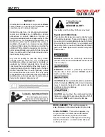
NOTICE !!!

Unauthorized modifications may present 

extreme


safety hazards to operators and bystanders and 

could also result in product damage.  

Schiller Grounds Care, Inc. strongly warns against, 

rejects  and  disclaims  any  modifications,  add-on 

accessories or product alterations that are not 

designed, developed, tested and approved by Schiller 

Grounds Care, Inc.Engineering Department.  Any 

Schiller Grounds Care, Inc.product that is altered, 

modified or changed in any manner not specifically 

authorized after original manufacture-including the 

addition of “after-market” accessories or component 

parts not specifically approved by Schiller Grounds 

Care, Inc.-will result in the Schiller Grounds Care, 

Inc.Warranty being voided.

Any and all liability for personal injury and/or 

property damage caused by any unauthorized 

modifications, add-on accessories or products not 

approved by Schiller Grounds Care, Inc.will be 

considered the responsibility of the individual(s) or 

company designing and/or making such changes.  

Schiller Grounds Care, Inc.will vigorously pursue 

full indemnification and costs from any party 

responsible for such unauthorized post-manufacture 

modifications and/or accessories should personal 

injury and/or property damage result.


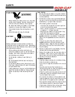
This symbol means:

 ATTENTION! 


BECOME ALERT!


Your safety and the safety of others is involved.

Signal word definitions

:

The signal words below are used to identify levels 

of hazard seriousness. These words appear in this 

manual and on the safety labels attached to Schiller 

Grounds Care, Inc.machines. For your safety and 

the safety of others, read and follow the information 

given with these signal words and/or the symbol 

shown above.


DANGER 

indicates an imminently hazardous 

situation which, if not avoided, 

WILL 

result in death 

or serious injury. 


WARNING 

indicates a potentially hazardous 

situation which, if not avoided, 

COULD 

result in 

death or serious injury. 


CAUTION

 indicates a potentially hazardous situation 

which, if not avoided, 

MAY 

result in minor or moderate 

injury. It may also be used to alert against unsafe 

practices or property damage.

CAUTION 

used without the safety alert symbol 

indicates a potentially hazardous situation which, if 

not avoided, 

MAY

 result in property damage

MODEL NUMBER:

  This number appears on 

sales literature, technical manuals and price lists.

SERIAL NUMBER: 

 This number appears only 

on your mower. It contains the model number 

followed consecutively by the serial number.  

Use this number when ordering parts or seeking 

warranty information.  Located behind rider pad 

on frame of unit.

Summary of Contents for BOB-CAT 912480A

Page 1: ... SD S N 1018 and higher 912521A BC QUICKCAT 4000 FT730V KAW EFI 52 SD S N 0000 and higher 912611A BC QUICKCAT 4000 FT730V KAW 61 SD S N 0000 and higher 912480AAU BC QUICKCAT 4000 FX651V KAW 48 SD S N 90103 and higher 912520AAU BC QUICKCAT 4000 FX691V KAW 52 SD S N 90100 and higher 912610AAU BC QUICKCAT 4000 FX730V KAW 61 SD S N 90100 and higher www bobcatturf com OPERATOR S PARTS MANUAL ...

Page 2: ...equipped with a spark arrestor as defined in Section 4442 maintained in effective working order or the engine is con structed equipped and maintained for the prevention of fire To acquire a spark arrestor for your unit see your Engine Service Dealer Please refer to the engine manufacturer s information included with the machine Labeled power ratings are supplied by the engine manufacturer in accor...

Page 3: ... Schiller Grounds Care Inc replacement parts because they are manufactured with the same high precision and quality as the original parts Schiller Grounds Care Inc designs and builds its equipment to serve many years in a safe and productive manner For longest life use this machine only as directed in the manuals keep it in good repair and follow safety warnings and instructions You ll always be g...

Page 4: ...ns and or accessories should personal injury and or property damage result This symbol means ATTENTION BECOME ALERT Your safety and the safety of others is involved Signal word definitions The signal words below are used to identify levels of hazard seriousness These words appear in this manual and on the safety labels attached to Schiller Grounds Care Inc machines For your safety and the safety o...

Page 5: ...tands the operator manual and understands the risks involved 2 Is sufficiently mature to use caution and 3 Is of sufficient size and weight to operate the controls comfortably and to manage the mower without taking risks All rotary lawnmowers are potentially dangerous They can amputate hands and feet and throw objects Failure to follow these safety and operating instructions could result in seriou...

Page 6: ...ge or damage to the engine or emissions system If fuel is spilled do not attempt to start the engine until the spill is cleaned up and vapors have cleared Replace caps on fuel containers and tanks se curely Do not operate without the entire exhaust system in place and in good working condition WARNING Under certain conditions static electricity can cause sparks during fueling and start fires or ca...

Page 7: ...king Slow down and use caution when making turns and crossing roads and sidewalks Stop blades when not moving Stop blades when crossing surfaces other than grass Do not mow with the discharge deflector raised removed or altered unless there is a grass collection system or mulch kit in place and working properly Do not start the cutting blades until you are ready to start mowing Use care when appro...

Page 8: ...n With zero turn machines mow across slopes not up and down If the machine will not stay on the slope it is too steep WARNING Mid mount zero turn belly mounted deck machines have much greater traction pointed up slope then down slope Be aware that traction may be lost going down a slope Do not operate a mid mount zero turn on slopes it cannot back up Avoid starting or stopping on a slope If tires ...

Page 9: ...iving the machine on a ramp as this could cause a loss of control or a tip over situation If applicable shut off fuel when transporting Secure the machine to the truck or trailer Hydraulic fluid can penetrate skin use paper to check for leaks Relieve hydraulic pressure before disconnecting hoses Make sure connections are tight and hoses are in good condition HYDRAULIC SYSTEM Hydraulic fluid escapi...

Page 10: ...he clamps do not touch anywhere except to intended metal parts Never connect a positive or red terminal to a negative or black terminal Make sure the cables won t get caught in any parts after the engines are started 4 Connect one end of the first jumper cable to the positive terminal on one battery Connect the other end to the positive terminal on the other battery 5 Connect one end of the other ...

Page 11: ...e ignition switch is OFF and the key has been removed before servicing the battery a Verify battery polarity before connecting or disconnecting the battery cables b When installing the battery always assemble the RED positive battery cable first and the ground BLACK negative cable last c Tighten cables securely to battery terminals and apply a light coat of silicone dielectric grease to terminals ...

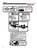
Page 12: ...nd Operation and Safety Manual if lost or damaged TRANSPORT CUT 4176581 WARNING WARNING ADVERTENCIA Leer el manual del operador No permitir que personas no capacitadas para ello usen la máquina Mantener los protectores en su lugar y sus tornillos debidamente fijados Antes de limpiar ajustar o reparar este equipo apagar todos los mandos aplicar el freno de estacionamiento y apagar el motor Mantener...

Page 13: ...11 QUICKCAT LABELS 4170653 TRANSPORT 4 1 2 1 3 4 2 1 4 3 1 4 3 3 4 23 4 4 1 1 2 2 2 1 2 3 3 1 2 4 1 4 TRANSPORT 4 1 2 4 3 2 3 1 2 2 1 2 1 1 2 1 3 4 2 1 4 2 3 4 3 1 4 3 3 4 4 1 4 4170988 ...

Page 14: ...CKCAT LABELS BELT ROUTING 4171408 SPRING LENGTH FOR WHEN INSTALLING NEW BELTS ONLY DO NOT READJUST AFTER USE 6 3 4 1 8 FRONT REFERENCE BAR ADJUSTMENT 4177207 OPERATOR S MANUAL LOCATED BEHIND RIDER PAD 4171344 ...

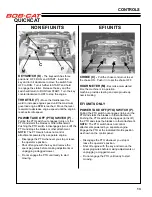
Page 15: ...ave the operator s position Shut off engine with the key and remove the spark plug wires before making adjustments or unplugging a clogged mower Do not engage the PTO until ready to start mowing CONTROLS CHOKE C Pull the choke control out to set the choke ON Push it in to set the choke OFF HOUR METER M Records accumulated time the machine is in operation machine provide steering and also provide d...

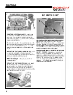
Page 16: ...sired height of cut Raise the deck to transport using the HOC handle Position pin A in the hole corresponding to the desired height of cut Lower the HOC handle until it rests on pin A OIL PRESSURE MALFUNCTION LIGHTS S Indicates low engine oil pressure when lit NOTE When starting the engine the indicator light will come on breifly as an engine system check If the light stays on after initial start ...

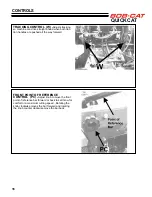
Page 17: ...ver OP CONTROLS Parking brake in ON position operator s right side PUSHING THE MACHINE The machine may be pushed with the engine off the parking brake off and the bypass valves open Bypass valves are located on the frame by the rider platform To open the bypass valves move the parking brake to any OFF position then lift and pull bypass control rod C through the large opening D until the control ro...

Page 18: ... tion handles are pushed all the way forward FRONT POINT OF REFERENCE CONTROL PC Adjust knob to move the front point of reference bar forward or back to set throw for comfort or a maximum cutting speed Rotating the knob clockwise moves the bar forward and rotating the knob counter clockwise move the bar back ...

Page 19: ... Overfill Install dipstick assembly firmly until cap bottoms out on tube Dipstick assembly must always be secured into fill tube when engine is running ___ Check all lubrication points and grease as instructed in manual ___ Check hydrostatic fluid level Check to be sure cooling fins on hydrostat are clean ___ Perform a functional check of the safety interlock system each time you operate the unit ...

Page 20: ...NGINE 1 Turn the key to operate the electric starter to start the engine Release the key when the engine starts 2 If the engine does not start immediately do not crank for more than 10 seconds at a time Allow 60 seconds for the starter motor to cool down between starting attempts to prevent the starter motor from burning out 3 If the choke is ON when the engine starts gradu ally back it off until ...

Page 21: ...nd a TRANSPORT speed Cut speed is limited to a maximum recommended speed to obtain a good quality cut Transport speed is limited to the maximum speed of the machine Decrease speed when traveling forward pulling the traction levers rearward slows the machine Stopping The machine will stop when the levers reach the neutral position Reverse movement To move the machine straight back pull both tractio...

Page 22: ...three rounds mow in the opposite direction left hand turns until finished If grass is extremely tall it should be mowed twice the first cut relatively high the second cut to the desired height Use the left side of the mower for trimming Choose cutting directions so that clippings are thrown onto areas that already have been cut This method results in the most even distribution of clippings and mor...

Page 23: ...he engine manual for additional information and instructions Check Top Off Oil Level X Check for Leaks X Clean Air Intake Screen X Clean Air Cleaner PreCleaner X Clean Air Cleaner Element X Clean Cooling Fins X Change Oil And Filter X See engine manufacturer s manual Check Replace Spark Plugs X TRANSAXLE CHANGE TRANSAXLE OIL AFTER INITIAL 75 100 HOURS Check Oil Level X X Check For Leaks X X Change...

Page 24: ...________________________________________________ ________________________________________________ ________________________________________________ ________________________________________________ MAINTENANCE RECORD DATE HRS DATE HRS DATE HRS DATE HRS DATE HRS DATE HRS GENERAL Check tire Pressures Lubricate All Points Check nuts Bolts ENGINE Check Oil Level Change Oil Clean Air Cleaner Element Clea...

Page 25: ...s and bolts found loose Replace any broken or missing cotter pins Repair any other problems before operating Tire pressure Rear Tires should be kept inflated at 12 lbs in2 84kg cm2 Improper tire inflation can cause rapid tire wear and poor traction Uneven inflation can cause uneven cutting Front tires should be 15p s i 1 05 kg cm BATTERY AGM TYPE BATTERY SUPPLIED Battery acid is caustic and fumes ...

Page 26: ...ts 1 3 with grease 1 Deck lift pivots 4 points 2 Deck idler pivot 1 point Every 500 hours or once a year 3 Caster wheel pivots 2 points NOTE ON BLADE SPINDLES The blade spindles on these machines use a superior sealed bearing that does not require re lubrication MAINTENANCE 2 1 1 3 ...

Page 27: ...LY 1 Check oil level with the dipstick 2 If oil is needed add fresh oil of proper viscosity and grade See engine manual for oil specifications Do not overfill 3 Replace dipstick before starting engine PERIODIC OIL CHANGES 1 See engine manual for oil and filter change inter vals after the break in period 2 Follow instructions for first oil change above SPARK PLUGS Remove each plug and check conditi...

Page 28: ... used oil in ac cordance with local requirements 2 Wipe the filter base surface off and apply a film of new oil to the gasket of the new replacement filter Install the new filter by hand turn 3 4 to one full turn after the filter gasket contacts the filter base surface 3 Re install the filter guard and torque the three screws to 65 in lbs each 4 Remove cap C fill the transaxles through the expansi...

Page 29: ...axle fluid fill to proper level if required Should be to the Full Cold Line 2 Raise the drive wheels off the ground Support unit with jack stands or other suitable means 3 Open bypass valves To open the bypass valves move the parking brake to any OFF position then lift and pull bypass control rod C through the large opening D until the control rod stop is past the opening Drop rod C into the small...

Page 30: ...eaner To replace 48 air cleaner elements 1 Unclamp end cover X and remove existing cleaner elements 2 Insert new elements Y and Z 48 ONLY and replace cover Ensure the breathing port A is pointing down and towards the front of the tractor To replace 52 61 air cleaner element 1 Turn knobs K a 1 2 turn and remove filter cover 2 Insert new element Y and replace cover NON EFI UNITS EFI UNITS MAINTENANC...

Page 31: ...ING BOLT 50 FT LBS 68 Nm TRANSAXLE PULLY BOLT 28 3 41 5 FT LBS 38 56 Nm TRANSAXLE DRAIN PLUG 15 20 FT LBS 20 27 Nm TRANSAXLE FILTER 100 150 IN LBS 14 6 16 9 Nm STORAGE INSTRUCTIONS To prevent possible explosion or ignition of vaporized fuel do not store equipment with fuel in tank or carburetor in enclosure with open flame for example a furnace or water heater pilot light Daily Storage 1 Check eng...

Page 32: ...Always use BOB CAT blades Use of another manufacturer s blades may be dangerous BLADE BALANCE Blade balance must be maintained at 5 8 oz in 19 4 g cm or less Failure to keep blades balanced causes excess vibration wear and shortened life of most components of the machine To balance a blade 1 Sharpen blade first 2 Balance the blade at the center 3 Attach a 1 8 oz 3 9 g weight at a distance 5 127 mm...

Page 33: ...cut lever E to that height 4 Loosen nuts on bolts G Move bolts in slot to remove slack in chain Tighten nuts on bolts G A 1 8 forward pitched deck provides the best horsepower A level deck provides the best quality of cut A 1 8 rearward pitched deck provides the best striping Certain grass types and conditions may vary HEIGHT OF CUT The height of cut is set by moving height of cut pin B to the hol...

Page 34: ... 1 Loosen the front bolts S 2 Adjust height of H 3 Retighten S once you have desired height Suggested heights for grass types Factory setting is all the way down Southern season grasses generally will work with the lip down When cutting Bahia grass or other grasses where seed pods grow higher then the actual grass blade you will want to adjust the lip all the way up Northern season grasses general...

Page 35: ...traight To adjust 1 Remove rider pad and locate the tracking ad justment knobs on the control mounting brack ets of the machine Turn both tracking adjust ment knobs counter clockwise until they stop 2 Gently push both traction control handles all the way forward with transport speed selected Turn the tracking adjustment knob clockwise until it touches the corresponding control arm so the tracking ...

Page 36: ...te the control rod B until both left and right handle is aligned with the slot on the control panel 4 Tighten the jam nuts A at the top and the bottom of the control rod B 5 Press the control lock rod D into the slot in the control and tighten nut C DAMPERS Dampers are provided on the traction controls to make it easier to operate the machine smoothly There is one on each side There are three moun...

Page 37: ...enter left and right belt guards 2 Set the cutterdeck in a middle height of cut posi tion 3 Loosen bolt on belt guide so belt guide can be moved to remove the belt 4 Insert 3 8 ratchet extension in hole A on the idler arm to back tensioning idler off to remove belt from idler Remove belt from cutterdeck pulleys 5 Remove belt from clutch pulley 6 Install the new belt by performing these steps in re...

Page 38: ...ontrol handle in the NEUTRAL position rotated up move the parking brake lever to OFF and turn the PTO Blades ON Each check should kill the engine after 1 2 second delay A 1 2 second delay is built into the system to prevent engine cut out when traversing rough terrain Repair machine before using if the Operator Pres ence Interlock System does not operate correctly in start or run Contact your auth...

Page 39: ...IGNITION SYSTEM Electronic Electronic Electronic CHARGING SYSTEM 15 amp regulated 15 amp regulated 15 smp regulated BATTERY BCI group U1 BCI group U1 BCI group U1 FUSES Two 20 amp blade Two 20 amp blade Two 20 amp blade EFI ENGINES MODEL NUMBER 912521 912611 MANUFACTURER Kawasaki Kawasaki MODEL F7301V FT730V CYLINDERS 2 2 COOLING Air Air BORE STROKE 3 1 X 3 0 78 X 76 mm 3 1 X 3 0 78 X 76 mm DISPLA...

Page 40: ...TIP SPEED 17773 ft min 5420 m min 3600 Engine RPM 18585 ft min 5665 m min 3600 Engine RPM 18850 ft min 5745 3600 Engine RPM ANTI SCALP ROLL ERS 4 4 7 SPINDLES Bottom mounted and maintenance free with 1 shaft in precision machined cast iron housing CUTTING HEIGHT PRODUCTION Height Lever allows easy setting of cut heights from 1 1 2 to 4 1 2 in 1 4 increments CONSTRUCTION Fabricated and welded 7 gau...

Page 41: ...39 QUICKCAT PARTS SECTION PARTS SECTION ...

Page 42: ...40 QUICKCAT FIGURE 1 ENGINE DECK ASSY 2 5 6 16 17 21 8 22 26 28 18 32 31 30 27 9 25 20 7 15 24 14 13 23 18 10 29 12 29 4 3 25 11 1 33 37 13 4 37 25 35 22 36 19 19 28 34 ...

Page 43: ...ICAL 1 17 64123 155 BLT HEX 7 16 20 X 3 1 18 64018 44 BLT CRG 3 8 16X1 NECK 5 19 4171826 WSHR 5 16 TEF 4 20 38304 03 BEARING FLANGED PLAS 1 21 64123 54 BLT HEX 5 16 18 X 75 4 22 64268 02 NUT FL NY LOCK 5 16 18 6 23 64001 6 NUT HEX JAM 3 8 16 4 24 64268 03 NUT FL NY LOCK 3 8 16 4 25 64263 007 BLT FLG HD M8 1 25 X 20 QTY 5 ON NON EFI ENGINES QTY 4 ON EFI ENGINES 26 64018 2 BLT CRG 1 4 20X3 4 2 USED ...

Page 44: ...42 QUICKCAT FIGURE 2 RIDER PLATFORM ASSY 15 7 15 15 13 16 14 18 10 16 3 9 20 2 6 8 11 19 12 17 5 4 16 16 18 1 22 21 ...

Page 45: ...670 MAT FOOTPLATE 1 9 4171672 BUMPER FOOTPLATE 2 10 4175836 LABEL BOB CAT 1 11 4166324 04 BEARING SLEEVE 2 12 4171254 SPACER 625X11GAX1 375 2 13 64229 10 NUT NYLON LOCK 10 24 4 14 64152 49 SCREW SLT HH 10 24X3 4 4 15 64018 44 BLT CRG 3 8 16X1 10 16 64268 03 NUT FL NYLON LOCK 3 8 16 12 17 64262 006 BLT FLG HD 5 16 18 X 3 4 1 18 64268 02 NUT FL NYLON LOCK 5 16 18 5 19 64262 027 BLT FLG HD 3 8 16 X 2...

Page 46: ...CAT FIGURE 3 WHEEL TRANSAXLE ASSY 5 5 14 3 2 1 10 7 8 22 21 39 41 40 38 23 19 24 9 26 28 25 25 37 32 42 30 13 31 12 11 29 23 14 36 17 20 18 20 16 34 33 26 42 27 28 36 37 20 18 20 17 30 13 31 12 11 27 29 4 6 35 ...

Page 47: ...ANSAXLE 2 16 4142808 TANK HYDR EXPAN W CAP 1 17 2690030 02 FTG 9 16 18 ORB X 1 2 2 18 4176445 01 TUBING 1 2ID CLEAR 15IN 2 19 64163 61 WSHR 81X 406X16GA 1 20 108094 12 CLAMP HOSE SAE6 4 21 64018 49 BLT CRG 3 8 16 X 1 1 2 1 22 64270 01 BLT HEX M10 1 5x30 1 23 64151 34 NUT HEX LOCK 3 8 16 JAM 3 24 33148 01 SPACER 0 379X0 750X0 25 1 25 64187 03 NUT WHEEL 1 2 20 8 26 64139 30 BLT WLFS 5 16 18 X 3 1 2 ...

Page 48: ...46 QUICKCAT FIGURE 4 FUEL TANK BATTERY ASSY 3 2 18 19 17 14 23 20 23 16 15 31 31 12 26 25 13 27 28 21 12 22 7 8 11 9 10 11 9 10 23 31 4 6 32 23 31 33 1 29 30 24 5 34 34 34 34 35 35 36 ...

Page 49: ...RY AGM 15 4168635 S BRKT BATTERY W LABS 1 INCLUDES ITEM 20 16 4171586 BUMPER RUBBER 1 17 64262 002 BLT FLG HD 1 4 20 X 3 4 2 18 64163 03 WSHR 256ID X 62OD X 18 GA 2 19 64025 01 1 4 20 HEX NUT 2 20 2000590 LABEL WARN BATTERY 1 21 2000570 LABEL WARN FUEL PICT 1 22 4162977 001 HOSE FUEL LINE 6 INCH 1 23 64123 49 BLT HEX 1 4 20 X1 2 4 24 64152 46 SCREW SLT HH 10 24X1 2 5 25 4174343 GROMMET ROLLOVER VE...

Page 50: ...48 QUICKCAT FIGURE 5 PARKING BRAKE ASSY 19 16 9 13 11 12 14 1 17 20 27 18 28 15 31 30 29 20 22 24 21 23 25 3 2 26 8 10 6 23 10 8 12 4 20 7 5 6 10 ...

Page 51: ...OTTER HAIRPIN 08 X 1 19 3 13 4170367 ROD PARKING BRAKE LOWER 1 14 64018 57 BLT CRG 5 16 18X6 1 15 64188 65 PIN CLEVIS 1 4 X 62 1 16 4168217 7 BRACKET CLIP RETAINER 1 17 4176179 7 BRKT PAKNG BRAKE UPPER 1 18 64123 12 BLT HEX 5 16 18X2 1 2 2 19 64025 02 NUT HEX 5 16 18 3 20 64268 02 NUT FL NYLON LOCK 5 16 18 5 21 4176054 WLDMNT SPD CNTRL HANDLE 1 22 4176120 KNOB 1 32 TAPERED 3 8 THRD 1 23 516544 BUS...

Page 52: ...BLACK G GREEN LG LIGHT GREEN GY GREEN W YELLOW STRIPE R RED RW RED W WHITE STRIPE BR BROWN BRY BROWN W YELLOW STRIPE Y YELLOW YB YELLOW W BLACK STRIPE 20A FUSE 2 BATTERY 20A FUSE 1 ENGINE CHARGING HOUR METER 6 SWITCH CLUTCH 4 BRAKE SWITCH 5 KEY SWITCH 2 OP PRES 5 7 7 BLADES TRACTION RELAY DELAY RELAY STARTER RELAY 8 8 8 CLUTCH RELAY 8 20A FUSE 2 20A FUSE 1 MODULE DELAY 3 ADAPTER 12V 12 B O O B 11 ...

Page 53: ...ULE DELAY 1 4 2721505 SWITCH PTO 1 5 2188156 SWITCH NONO DBL POLE 2 6 4177930 METER HOUR MAG SENSOR 1 7 4173756 FUSE 20 AMP MINI 2 8 4173755 RELAY SPDT MICRO 4 9 64018 41 BLT CRG 1 4 20 X 5 8 3 10 64268 01 NUT FL MYLON LOCK 1 4 20 3 11 4176734 HARNESS JUMPER FUEL GAUGE 1 12 4176839 GAUGE FUEL 1 NOT ILLUSTRATED FIGURE 6 UPPER WIRE HARNESS ...

Page 54: ... B B P RW ENGINE GROUND CLUTCH STARTER SOLENOID ENGINE CHARGING ENGINE KILL WB G GREEN PURPLE P RW RED W WHITE STRIPE STARTER SOLENOID R YB R RW P WB B G BL B B YELLOW W BLACK STRIPE YB CARB SOLENOID 5 2 3 4 1 2 SOLENOID 3 BLACK 7 GROUND ENGINE BLOCK BATTERY RED 9 SOLENOID BATTERY 8 6 TO SOLENOID 2 RED 10 4 10 3 4 1 10 ...

Page 55: ...ECTRICAL 1 3 38665 SOLENOID 1 4 108061 04 CABLE BATTERY 20 RED 1 5 2720949 ASSY CLUTCH WIRE 1 6 4171099 BATTERY 190CCA 1 4171973 CHARGER BATTERY AGM 7 30 419 CABLE BATTERY BLACK 29 1 8 112386 BOOT BATTERY TERM POS 1 9 2722227 02 CABLE BATTERY W CONDUIT 1 10 2308095 COVER TERMINAL 3 FIGURE 7 NON EFI 48 52 LOWER WIRE HARNESS ...

Page 56: ...UE WHITE W BLACK STRIPE WIRE BL B YB B B P RW ENGINE GROUND CLUTCH STARTER SOLENOID ENGINE CHARGING ENGINE KILL WB G GREEN PURPLE P RW RED W WHITE STRIPE R YB R RW P WB B G BL YELLOW W BLACK STRIPE YB CARB SOLENOID 5 2 3 BLACK 7 GROUND ENGINE BLOCK BATTERY RED ENGINE BATTERY 8 6 4 ...

Page 57: ...2 4171141 CLUTCH ELECTRIC 1 3 2722227 02 CABLE BATTERY W CONDUIT 1 4 2308095 COVER TERMINAL 1 5 2720949 HARNESS CLUTCH JUMPER 1 6 4171099 BATTERY 190CCA 1 4171973 CHARGER BATTERY AGM 7 30 419 CABLE BATTERY BLACK 29 1 8 112386 BOOT BATTERY TERM POS 1 NOT ILLUSTRATED FIGURE 8 NON EFI 61 LOWER WIRE HARNESS ...

Page 58: ...LE DIAL TO ENGINE 13 4 O 2 O 3 RB PI BR 1 3 O 4 B 3 LG 1 3 O 4 B 3 LG P W BW 1 BW 1 W P WB G YB BR RB PI A S H J R B 1 B 2 LB BW 2 DB 2 GRA LB BW 2 B 2 DB 1 DB 2 G M F R G O 1 B 1 YB WB DB 1 A SOFT START MODULE 12 WIRE COLORS B BLACK BR BROWN BW BLACK W WHITE STRIPE DB DARK BLUE G GREEN GRA GRAY LB LIGHT BLUE LG LIGHT GREEN O ORANGE P PURPLE PI PINK R RED RB RED W BLUE STRIPE W WHITE WB WHITE W BL...

Page 59: ...1 5 2720949 ASSY CLUTCH WIRE 1 6 4177381 BATTERY U1 12V 300CCA 1 7 30 419 CABLE BATTERY BLACK 29 1 8 112386 BOOT BATTERY TERM POS 1 9 2722227 02 CABLE BATTERY W CONDUIT 1 10 2308095 COVER TERMINAL 3 11 4177930 HOUR METER MAG SENSE 1 12 4169459 CONTROL SOFT START 1 13 148082 10 FUSE 10 AMP 1 14 64152 46 SCREW SLT HH 10 24X1 2 1 15 64229 10 NUT NYLON LOCK 10 24 1 16 4177904 HARNESS JUMPER EFI 1 USED...

Page 60: ...UICKCAT FIGURE 10 TOWER ASSY 21 4 10 7 9 5 11 6 3 16 8 27 2 15 24 22 25 26 16 31 15 11 11 11 23 15 22 23 31 13 13 13 13 14 14 14 14 15 20 1 18 19 12 15 21 26 20 19 20 18 20 17 22 22 17 16 16 28 29 30 17 32 ...

Page 61: ...8 00 LONG 1 13 64262 007 BLT FLG HD 5 16 18 X 1 4 14 64018 44 BLT CRG 3 8 16X1 SN 4 15 64268 03 NUT FL NYLON LOCK 3 8 16 6 16 64268 01 NUT FL NYLON LOCK 1 4 20 5 17 64018 41 BLT CRG 1 4 20 X 5 8 3 18 64123 70 BLT HEX 3 8 16X1 1 2 2 19 4176287 01 BEARING SMALL SLF ALGN 2 20 64268 02 NUT FL NYLON LOCK 5 16 18 4 21 4116380 01 SPACER 272X 438X 635 4 22 64018 51 BLT CRG 5 16 18 X 3 4 SN 4 23 64229 08 N...

Page 62: ...60 QUICKCAT RIDER PAD FENDER ASSY FIGURE 11 2 1 5 5 15 14 11 12 13 15 6 7 7 15 13 10 4 3 17 18 9 8 17 18 19 16 20 21 22 15 23 23 18 ...

Page 63: ...NT TUBE LABEL 1 9 2000735 LABEL OPER MAN 1 10 38061A CAP BLACK VINYL 1 11 64262 007 BLT FLG HD 5 16 18 X 1 2 12 4170388 SPACER FOOTPLATE LATCH 2 13 64268 01 NUT FL NYLON LOCK 1 4 20 3 14 64018 15 BLT CRG 5 16 18X1 SN 6 15 64268 02 NUT FL NYLON LOCK 5 16 18 10 16 64018 2 BLT CRG 1 4 20X3 4 1 17 64123 114 BLT HEX 1 4 20X1 3 18 64006 01 LOCKWSHR 1 4 HELICAL 6 19 64163 02 WSHR 321X 593X11GA 2 20 41758...

Page 64: ... 6 3 35 25 29 6 21 27 7 22 36 40 20 17 34 33 18 30 15 13 4 5 14 30 16 28 25 23 32 12 41 2 39 11 24 19 10 38 37 43 42 31 46 49 48 47 45 50 49 48 47 45 50 51 20 20 21 39 51 20 17 23 41 2 39 19 10 37 44 1 38 NON EFI MODEL EFI MODELS 44 12 25 24 52 ...

Page 65: ...3 64268 05 NUT FL NYLON LOCK 1 2 13 2 24 64152 46 SCREW SLT HH 10 24X1 2 QTY 2 ON NON EFI MODELS QTY 1 ON EFI MODELS 25 64025 15 NUT HEX 10 24 KEPS QTY 4 ON NON EFI MODELS QTY 1 ON EFI MODELS 26 64025 03 NUT HEX 5 16 2424 2 27 64025 33 NUT HEX 5 16 24 LH 2 28 64262 013 BLT FLG HD 3 8 16 X 1 1 2 2 29 64262 027 BLT FLG 3 8 16 X 2 1 4 1 30 64268 03 NUT FL NYLON LOCK 3 8 16 3 31 64163 31 WSHR 25 64X1X...

Page 66: ...64 QUICKCAT FIGURE 13 DECK LIFT ASSY HOC 5 3 2 1 16 21 20 19 17 13 12 15 11 14 10 9 8 7 6 2 19 21 20 17 21 14 2 2 26 21 24 22 28 25 26 27 4 18 23 ...

Page 67: ...E 1 11 4170653 LABEL HOC 1 12 4170988 LABEL HOC 1 13 2183071 05 SPACER 2 14 64262 027 BLT FLG HD 3 8 16 X 2 1 4 GR8 2 15 4177355 ASSY PIN LANYARD 1 16 4167826 ROD DECK LIFT 2 17 64221 04 E RING 875 4 18 4176557 7 WLDMT HOC HANDLE TOP 1 19 4169126 01 CHAIN 6 35 250 7 LINKS 4 20 64123 281 BLT HEX 1 2 13X2 FLL THRD 8 21 64141 13 NUT WLF 1 2 13 16 22 64229 06 NUT NYLON LOCK 5 8 11 2 23 4168424 ZERK 1 ...

Page 68: ...66 QUICKCAT FIGURE 14 CASTER ASSY 9 16 15 5 4 2 4 5 6 8 18 19 12 11 10 12 7 20 21 3 23 22 17 1 14 13 25 24 27 26 26 27 ...

Page 69: ...4 7 WLDMT CASTER YOKE 2 8 64140 5 COTTER PIN 1 4 2 2 9 4162986 CAP END 2 10 4175255 ASSY WHEEL 13X6 5 6 BLK 2 11 2722230 03 SPANNER 13X6 5 WHEEL 2 12 2722231 SPACER END 4 13 4177357 7 COVER BELT CNTR 1 14 38524 KNOB 4 PRONG 3 8 16 1 15 64209 17 WSHR CON SPRNG 75X1 5 2 16 64025 20 NUT HEX 3 4 16 SLOT U 2 17 85010N ZERK 1 4 28 STR SLF THD 2 18 64123 223 BLT HEX 3 4 10X10 2 19 64229 07 NUT NYLON LOCK...

Page 70: ... FIGURE 15 48 SIDE DECK ASSY 34 32 23 51 16 47 46 3 17 51 20 19 28 31 14 12 13 15 11 9 10 7 8 27 39 54 52 44 6 48 37 5 56 38 50 53 41 43 40 26 41 55 42 48 22 21 25 22 2 45 4 24 48 36 30 29 35 30 29 48 33 34 49 18 ...

Page 71: ...959 2 SHAFT SPINDLE LONG 3 25 4175082 5 SPINDLE SPACER 1 767 3 26 2000572 LABEL WARNING BLADES 1 27 64018 34 BLT CRG 5 16 18 X 1 1 2 1 28 4128002 CAP 26 X 7 END 1 29 2721512 ROLLER 5X2 75 CENTERED 4 30 2720685 SPACER ROLLER 4 31 64270 02 BLT HEX M10 1 5x30 1 32 4163802 02 SPACER 1 0 X 516 X 1 3 16 1 33 64229 02 NUT NYLON LOCK 5 16 18 1 34 64141 6 NUT WLF 5 16 18 2 35 64123 173 BLT HEX 3 8 16X4 1 2...

Page 72: ...CAT FIGURE 16 52 SIDE DECK ASSEMBLY 22 21 25 22 24 2 4 5 53 38 47 46 3 37 51 20 19 6 44 14 13 31 12 28 10 11 7 8 15 23 51 16 26 32 39 34 49 18 33 45 50 36 45 30 29 30 29 35 45 34 45 9 17 27 41 40 42 43 52 26 41 ...

Page 73: ...BLT HEX 3 8 16X1 1 2 GR8 18 24 4174959 2 SPINDLE SHAFT 6 26IN 3 25 4175082 5 SPINDLE SPACER 1 767 3 26 2000572 LABEL WARNING BLADES 1 27 64018 34 BLT CRG 5 16 18 X 1 1 2 1 28 4128002 CAP 26 X 7 END 1 29 2721512 ROLLER 5X2 75 CENTERED 4 30 2720685 SPACER ROLLER 4 31 64270 02 BLT HEX M10 1 5x30 ISO 1 32 4163802 02 SPACER 1 0 X 516 X 1 3 16 1 33 64229 02 NUT NYLON LOCK 5 16 18 1 34 64141 6 NUT WLF 5 ...

Page 74: ...IGURE 17 61 SIDE DECK ASSEMBLY 14 3 43 42 55 23 27 26 40 53 13 53 12 11 48 32 31 29 34 30 33 46 10 9 6 45 16 53 17 8 7 50 52 24 28 25 22 26 27 40 44 56 5 18 21 20 21 54 40 15 47 49 48 19 40 35 39 38 37 51 36 36 41 2 ...

Page 75: ...HEX 1 2 13X3 2 25 64141 13 NUT WLF 1 2 13 4 26 2721512 ROLLER 5X2 75 CENTERED 5 27 2720685 SPACER ROLLER 5 28 4163332 ROLLER ANTI SCALP 2 29 4170610 7 WLDMT IDLER ARM 1 30 4128004 BEARING BALL 10 X 26 X 8 1 31 548138 BRG NDL 88 1 12 1 00 1 32 521438 GREASE SEAL 1 33 64144 40 SNAP RING 26MM INTERNAL 1 34 85010N ZERK 1 4 28 STR SLF THRD 1 35 4164269 LABEL WARNING THROWN 1 36 2000577 DECAL ROTATING P...

Page 76: ...IGURE 18 48 52 CHUTE BAFFLES EDGES ASSY 43 4 9 8 7 22 3 21 12 14 11 15 11 12 30 13 28 25 24 27 23 19 31 10 2 18 16 17 2 29 26 20 2 2 2 2 5 5 34 34 33 34 13 26 25 37 39 37 39 38 38 38 1 37 32 36 35 32 41 40 42 6 30 4 ...

Page 77: ...176141 7 BAFFLE FRONT LH 52 1 18 4168527 7 BAFFLE FRONT RH 48 1 4168516 7 BAFFLE FRONT RH 52 1 19 64018 7 BLT CRG 3 8 16X1 1 4 2 20 64163 61 WSHR 81X 406X16GA 2 21 64018 9 BLT CRG 5 16 18X3 4 G5 2 22 4172339 PAD WEAR TRIM SIDE 1 23 4173063 7 PLATE CHUTE 1 24 4172328 CHUTE DISCHARGE 1 25 4169895 WASHER FRICTION UHMW 2 26 4169871 WASHER BELLVILLE 382 ID 2 27 4177410 7 BRKT CHUTE REAR 1 28 4177411 7 ...

Page 78: ...76 QUICKCAT FIGURE 19 61 CHUTE BAFFLES EDGES ASSY 35 22 3 21 12 14 11 15 11 12 32 34 33 32 30 13 28 25 24 27 23 19 31 10 2 18 16 17 29 26 20 2 2 2 5 13 26 25 1 2 2 38 4 9 8 7 36 37 6 30 4 ...

Page 79: ...2 EXTENSION DECK 61IN RH 1 16 4176065 7 BAFFLE FRONT CNTR 61 1 17 4176064 7 BAFFLE FRONT LH 61 1 18 4176066 7 BAFFLE FRONT RH 61 1 19 64018 7 BLT CRG 3 8 16X1 1 4 2 20 64163 61 WSHR 81X 406X16GA 2 21 64018 9 BLT CRG 5 16 18X3 4 G5 2 22 4172339 PAD WEAR TRIM SIDE 1 23 4173063 7 PLATE CHUTE 1 24 4172328 CHUTE DISCHARGE 1 25 4169895 WASHER FRICTION UHMW 2 26 4169871 WASHER BELLVILLE 382 ID 2 27 41774...

Page 80: ...SCHILLER GROUNDS CARE INC ONE BOB CAT LANE P O BOX 469 JOHNSON CREEK WI 53038 920 699 2000 www schillergc com Schiller Grounds Care Inc 2010 ...

Reviews: