background image

9

Hydro 

Midsize

CONTROLS

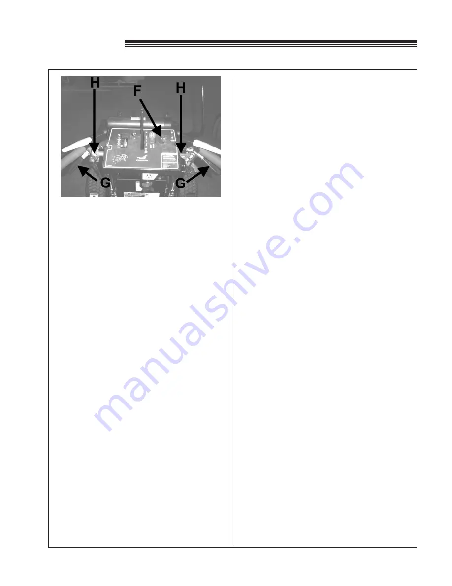
KEYSWITCH (F)

Recoil models:  Turn to right to allow engine to be 

started.  Turn key to left to stop engine.

Electric start models: Turn key to right and hold until 

machine starts.  When machine starts, let go of key 

and it will return to run position.  Turn key to left to 

stop engine.

TRACTION CONTROL LEVERS  (G)

TRACTION LOCKS (H)


The traction locks provide a neutral position when 

pulled back and locked with traction control levers.

To release

: pull the traction control levers up enough 

to push forward on the locks.

NOTE

  Squeezing the traction levers past the neutral 

position will cause the machine to back up)

  Both traction control levers must be released 

at the same time in order to go straight ahead.  

Using one traction control lever will cause the 

machine to turn to one side.

  When using the locks to provide a neutral position 

be sure the traction control rods are fully seated in 

the rear notch of the traction locks.  Failure to do 

this may result in serious injury.

The traction control levers have 

five

 functions:

1

.  To provide a neutral position to stop the machine 

or to start the engine.  Squeeze the levers enough 

to engage the traction lever locks by moving the 

tops of the locks towards the handgrip, then re-

lease the levers.

2

.  To engage the drive to wheels: gradually release 

the traction control levers to the speed set by the 

speed control and throttle.

3

.  To stop: pull the levers up to neutral.

4

.  To steer the unit: pulling up on the R.H. lever will 

initiate a R.H. turn and pulling up on the L.H. lever 

will initiate a L.H. turn.

5

.  To back up: squeeze the levers equally past    

neutral.  This may be done any time the engine 

is running and the speed selector is not set in 

neutral, allowing instant forward/reverse operation 

and zero turning with one wheel driving forward 

and one wheel driving backward.  Releasing the 

traction lever from reverse automatically returns 

the machine to neutral or the preset forward 

speed, depending on where the traction locks are 

set.

NOTE:

  There is a noticeable difference in the force 

required at the traction levers in the transition from 

neutral to reverse.

Summary of Contents for BOB-CAT 933305G

Page 1: ... 11 2010 PARTS MANUAL 4165108 933305G 36 HYDRO MID 16HP KAW FS 933307G 36 HYDRO MID 18HP ES KAW FS 934306G 48 HYDRO MID 18HP KAW FS 934307G 48 HYDRO MID 18HP ES KAW FS 935308G 54 HYDRO MID 20HP KAW FS 935309G 54 HYDRO MID 20HP ES KAW FS ...

Page 2: ...ado de California hace saber que los gases de escape de los mo tores diesel y algunos de sus com ponentes producen cáncer defectos de nacimiento y otros daños en el proceso de reproducción humana L émission du moteur de ce matériel contient des produits chimiques que l Etat de Californie considère être cancérigènes provoquer des défauts congénitaux et d autres dangers en matière de reproduction El...

Page 3: ...au tions Follow all instructions and warnings completely Do not remove or defeat any safety features Make sure those who operate this machine are as well informed and careful in its use as you are See a Schiller Grounds Care Inc dealer for any service or parts needed Schiller Grounds Care Inc service ensures that you continue to receive the best results possible from Schiller Grounds Care Inc prod...

Page 4: ...cts not approved by Schiller Grounds Care Inc will be considered the responsibility of the individual s or company designing and or making such changes Schiller Grounds Care Inc will vigorously pursue full indemnification and costs from any party responsible forsuchunauthorizedpost manufacturemodifications and or accessories should personal injury and or property damage result This symbol means AT...

Page 5: ...3 Hydro Midsize LABELS Manufactured under one or more of the following U S patents 5 343 678 5 415 059 5 651 241 4165666 ...

Page 6: ...4 Hydro Midsize LABELS For use on 933307G 934307G 935309G For use on 933305G 934306G 934308G ...

Page 7: ...5 Hydro Midsize LABELS ...

Page 8: ...o vibrate abnormally check immediately for the cause Vibration is generally a warning of trouble Beforeusingmachineforthefirsttime checkengine and hydraulic fluid levels and lubricate all points TRAINING a Readtheoperator smanualcarefully Allrotarygrass cuttersarepotentiallydangerous Nopersonshould operate the machine unless they are familiar with the controls and the proper use of the machine b N...

Page 9: ...Avoid ground conditions which will cause the machine to slide If the operator is uncomfortable or unsure of the machinesstability operationontheseslopesshould cease immediately The ultimate responsibility for safe operation on slopes rests with the operator Use lower speeds and exercise extreme caution on slopes and especially in sharp turns to prevent tipping and loss of control Use extra caution...

Page 10: ... speed is increased until the maximum governed rpm is obtained By moving the throttle lever fully back the engine will Idle down On engines with an integrated choke Moving the throttle lever forward to the detent gives maximum governed rpm Moving it past the detent chokes the engine SPEED SELECTOR E The speed selector levers in the center of the control panel set the maximum forward and reverse sp...

Page 11: ...this may result in serious injury The traction control levers have five functions 1 To provide a neutral position to stop the machine or to start the engine Squeeze the levers enough to engage the traction lever locks by moving the tops of the locks towards the handgrip then re lease the levers 2 To engage the drive to wheels gradually release the traction control levers to the speed set by the sp...

Page 12: ...l completely familiar with the controls For normal cutting the throttle should be set at the full open position By using the speed control lever to speed up or slow down the machine during use maximum control and cutting efficiency can be maintained Using the machine at less than full throttle in heavy conditions will cause the engine to labor and result in excessive wear For maneuvering where the...

Page 13: ...cks in neutral position 3 Disengage the cutterdeck with PTO switch 4 Move speed control to neutral 5 Close the throttle to slow the engine turn engine off with the keyswitch NOTE When the machine is transported by truck or trailer or left to stand unused the fuel valve under the fuel tank should be turned off This avoids the possibility of flooding should any dirt get under the carburetor float ne...

Page 14: ...ING THE MACHINE WITH THE ENGINE STOPPED Open dump valve V on each pump by turning counter clockwise two revolutions Move the machine and close dump valve V by turning clockwise until valve is firmly seated MACHINE OPERATION ...

Page 15: ...rs above or below wheel support bracket and replace the quick pin P 2 CUTTERDECK BLADE SPINDLES NOTE See MAINTENANCE section of the Setup Parts Maintenance manual for blade removal and replacement procedures 1 Remove belt cover 2 Remove nut N from the top of the cutter spindle bolt 3 Withdraw the cutterdeck spindle bolt from bottom complete with washer blade and spacers 4 Place the required number...

Page 16: ...er both outside edges of cutter deck at B See Block chart below 3 Remove 2 upper deck mounting bolts C 4 Loosen 2 lower deck mounting bolts D several turns Loosen enough to allow easy movement of the rear of cutterdeck Allow deck to set down on blocks or if deck is being raised allow the front casters to sit on the floor 5 Reinstall upper deck mounting bolts C according to the chart for the cut he...

Page 17: ...han back of blade to prevent double cutting Adjustment is provided by removing 1 8 washer beneath caster support FIXED CUTTERDECK HEIGHT OF CUT UPPER BOLT POSITION 111 4 375 6 1 1 4 625 118 1 1 6 CUTTING HEIGHT 2 625 3 625 4 125 3 875 3 375 3 125 2 875 1 875 2 375 2 125 1 625 1 375 IN 67 0 1 92 105 98 79 86 73 0 1 1 1 0 0 1 1 1 1 1 1 48 54 60 35 41 MM 1 1 1 1 0 0 A 1 1 B 1 1 2 5 5 5 3 3 3 0 2 2 C ...

Page 18: ...h 2 Disconnect the clutch wire harness 3 Unbolt clutch bracket from clutch and rotate the clutch to allow enough clearance to remove the clutch bracket 4 Rotate idler arm using a 3 8 ratchet or breaker bar inserted into the square hole in the idler arm 5 Remove pump drive belt 6 Replace by following steps in reverse order PTO BELT 1 Rotate idler arm using a 3 8 ratchet or breaker bar and remove be...

Page 19: ...f before proceeding to steps 2 and 3 STEP 2 Adjust Speed Control Rods First adjust neutral as outlined in Step 1 Set speed control levers to neutral Adjust swivels on lower ends of speed control rods R so they just go into top of the slots on the neutral plates NOTE If the speed control levers do not have adequate tracking adjustment the swivel on one of the rods needs to be turned 1 turn STEP 3 A...

Page 20: ... The brake should initially be adjusted so that the brake rod extends through swivel B 1 as shown If more brake pressure is required adjust as necessary 3 Reassemble brake rod to the brake lever using hairpin A 4 Apply parking brakes and try to push the machine forward If wheels rotate readjust brakes 5 Close bypass valves on the hydraulic pumps Speed Control Lever Friction The speed control lever...

Page 21: ...O ADJUST 1 Loosen clamp bolts on both ends G so clamps can rotate on shaft 2 Rotate actuator lever to depress switch plunger Keep OP levers against handles and tighten bolts G 3 When released the OP levers should rise and the actuator lever should rotate away from the switch allowing the switch plunger to extend completely HANDLE BAR HEIGHT ADJUSTMENT To adjust handle bar height Remove bolts G and...

Page 22: ... Raise rear of unit so that drive tires are off the ground Support the unit with jack stands 3 Remove wheel lug nuts and wheels Reattach wheels with the tires rotated so the wheel offset is the opposite of when they were previously installed 4 Lower machine off of the jack stands and torque wheel lug nuts to 85 ft lbs TIRE PRESSURE ADJUSTMENT Tire pressures should be maintained at 14 psi 1 0 kg cm...

Page 23: ...rolled drive wheels CUTTERDECKS CONSTRUCTION 10 and 7 gauge steel deck welded single unit baffled for high velocity air flow large discharge opening with chute guard deflector SPINDLES 1 spindle shaft on maintenance free sealed ball bearings in precision machined housing CASTERS 9 x 3 50 4 fixed decks only 11 x 4 00 5 floating decks only HEIGHT OF CUT adjustable from 1 3 8 to 4 5 8 3 5 11 7 cm BLA...

Page 24: ... 8 1 m m 7 5 4 5 2 6 1 m m 3 1 4 8 1 m m 7 5 4 E P Y T E D A L B t f i L h g i H n o i t p o t f i L w o L t f i L h g i H n o i t p o t f i L w o L t f i L h g i H n o i t p o t f i L w o L E D A L B S S E N K C I H T 5 0 2 0 m m 2 5 5 0 2 0 m m 2 5 5 0 2 0 m m 2 5 D E E P S P I T n i m t f 5 6 9 6 1 n i m m 1 7 1 5 n i m t f 5 1 3 5 1 n i m m 8 6 6 4 n i m t f 5 6 9 6 1 n i m m 1 7 1 5 Y L I A D...

Page 25: ... N m 2400 rpm OIL CAPACITY 1 8 qt 1 7L 1 8 qt 1 7L 1 8 qt 1 7L 1 8 qt 1 7L 1 8 qt 1 7L LUBRICATION Full Pressure Full Pressure Full Pressure Full Pressure Full Pressure CYLINDER BLOCK Aluminum with cast iron sleeve Aluminum with cast iron sleeve Aluminum with cast iron sleeve Aluminum with cast iron sleeve Aluminum with cast iron sleeve CYLINDER HEAD Aluminum Aluminum Aluminum Aluminum Aluminum GO...

Page 26: ...SCHILLER GROUNDS CARE INC ONE BOB CAT LANE P O BOX 469 JOHNSON CREEK WI 53038 920 699 2000 www schillergc com Schiller Grounds Care Inc 2010 ...

Reviews: