15
430
MAX
OPERATION
DRIVING
1. Select desired engine speed with the throttle. For
power driven attachments, the engine is normally
run at maximum RPM.
2. Vary vehicle speed with the Forward - Reverse
control lever. If the attachment or a steep slope
causes excessive drop in engine RPM; reduce
ground speed.
Do not lug the engine at
reduced RPM
.
3. Operate mower and other similar front mounted
attachments with front lift lever in “FLOAT”
position.
3. Safety seat switch requires operator to be seated
when PTO is “ON” or engine will stop. Disengage
PTO before attempting to start engine.
4. The hydrostatic transmission provides a braking
action when the Forward - Reverse control lever is
returned to neutral.
5. Set parking brake and stop engine before
dismounting.
6.
DO NOT TOW!
Serious damage to hydraulic
system will result. See below for emergency
moving instructions.
EMERGENCY TOWING INSTRUCTIONS
FOR A STALLED UNIT
1. Both transaxles must be in neutral before moving
a stalled unit. Neutral position is between HIGH
(2) and LOW (1) range position.
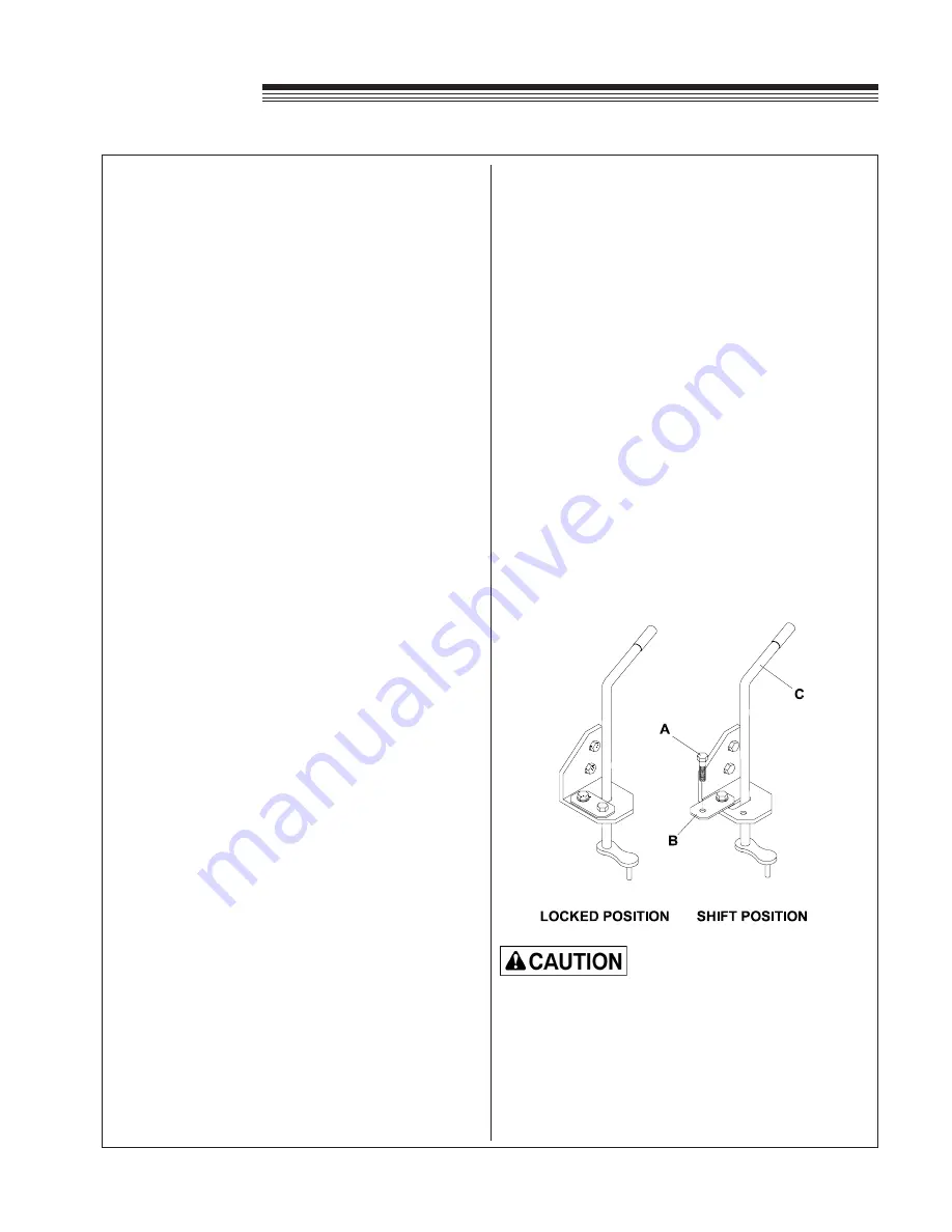
2. Release the locking straps
B
on both transaxles to
shift into "Neutral".
Failure to shift transaxles into "Neutral" will
cause serious damage to the hydrostatic
system.
3. Remember to lock the lever lock strap after
towing.
HIGH-LOW RANGE SELECTION
A locking device has been installed on the gear
range selector levers. The units are shipped with
the transaxle gear range selector in HIGH (2) range.
This range selection is recommended for most of
the operating tasks. If slower speeds and more
responsive F-R control is needed, use LOW (1)
range selection.
INSTRUCTIONS FOR TRANSAXLE
RANGE SELECTION
Do not attempt to select ranges on slopes or
when the unit is traveling. Select ranges only
on level surfaces.
1. Stop the unit on a level surface and set PARKING
BRAKE.
2. Stop the engine and dismount.
3. Remove the 1/4 x 3/4 flange bolt
A
from the lever
lock strap
B
and swing it away from the lever,
revealing a slot. (see diagram below)
4. Shift the range selector lever
C
, observing the
2 - N - 1 decal for range selection. A slight rocking
motion of the unit may be needed to fully engage
the selector.
5. With the selection completed, replace the lock
strap
B
and tighten the 1/4 x 3/4 flange bolt
A
to 12 - 15 ft. lbs. torque. (See Locked Position
drawing.)
6. Repeat step 3, 4, and 5 for the other transaxle.
Be sure to shift both transaxles into the same
range or serious mechanical damage will result!
DO NOT OPERATE UNIT WITHOUT THE LEVER
LOCK STRAPS IN THE LOCKED POSITION!


