Commissioning
©
by Antriebs- & Regeltechnik Schimpf GmbH
17
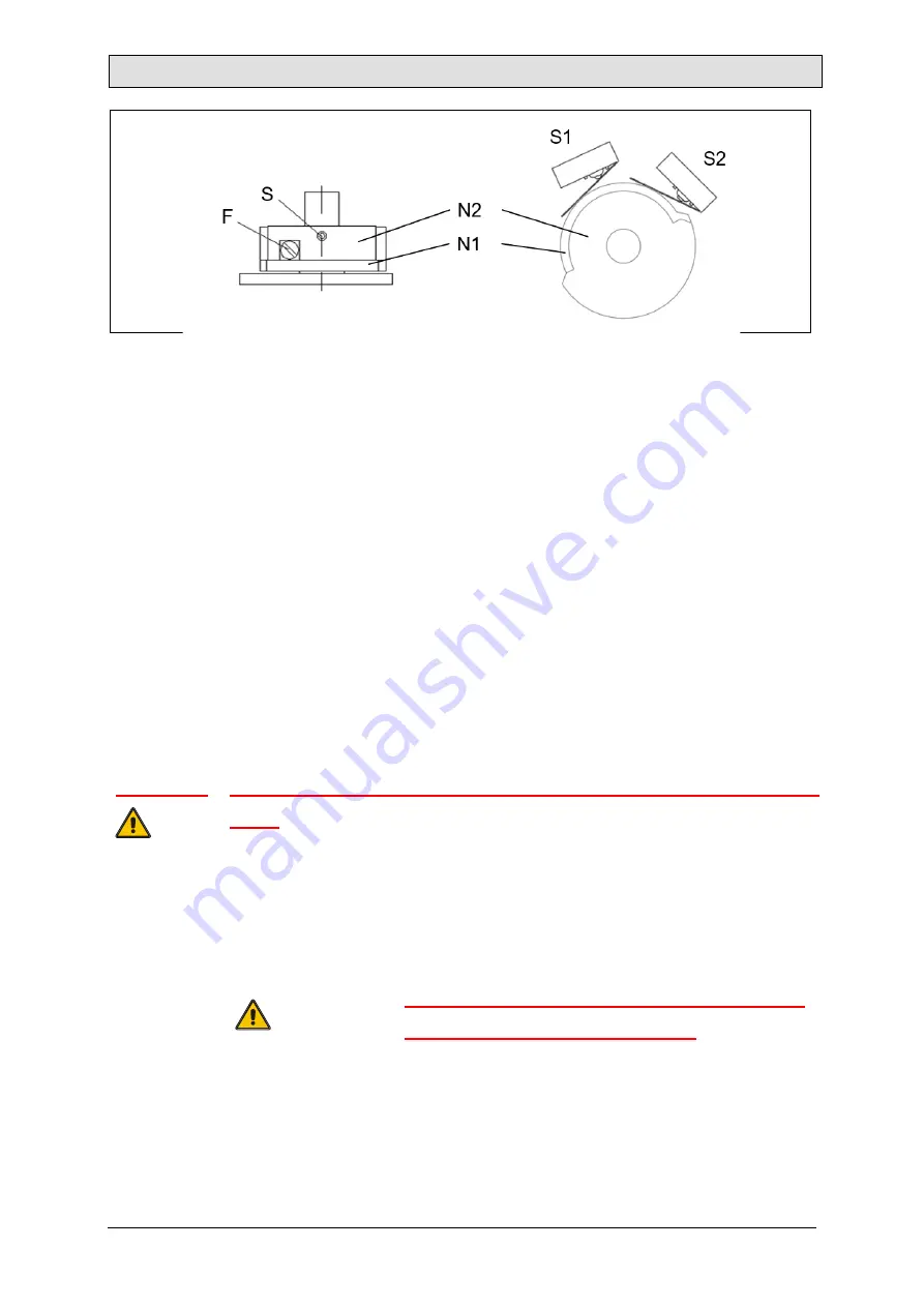
Figure 2: Overview of cam switch 00-10
The camshaft with cam discs
N1
and
N2
is fixed on the drive shaft with stud bolt
S
.
Cam disc
N2
is always firmly connected to the camshaft. Cam disc
N1
can be moved
relative to the camshaft using the adjusting screw
F
. The switch
S1
evaluates the
position of cam disc
N1
, while switch
S2
evaluates the position of cam disc N2.
The settings of the cam discs for the two switches influence each other. As a result,
the following procedure must be followed when setting the cam discs.
Restriction due to the narrow design: With a standard opening angle of 90°, both
positions cannot be below 25° at the same time. Likewise, both positions must not be
above 65° at the same time.
Important:
Switch off the power supply whenever you adjust the device with
tools.
The cam switches of model 00-10 are located on the underside of the add-on board.
The following illustrations are still shown from a top-down perspective looking in the
direction of the position indicator.
All cables connected to the drive must be
disconnected from mains power!


