MVPHD-24 Operations Manual Version 0.9.0 page 41 of 74
October 26, 2020
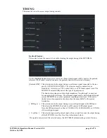
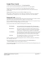
TIMING:
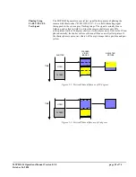
This menu tab is used to access output timing controls.
Genlock Source:
This control selects the source to be used for locking the output timing of the MVPHD-24.
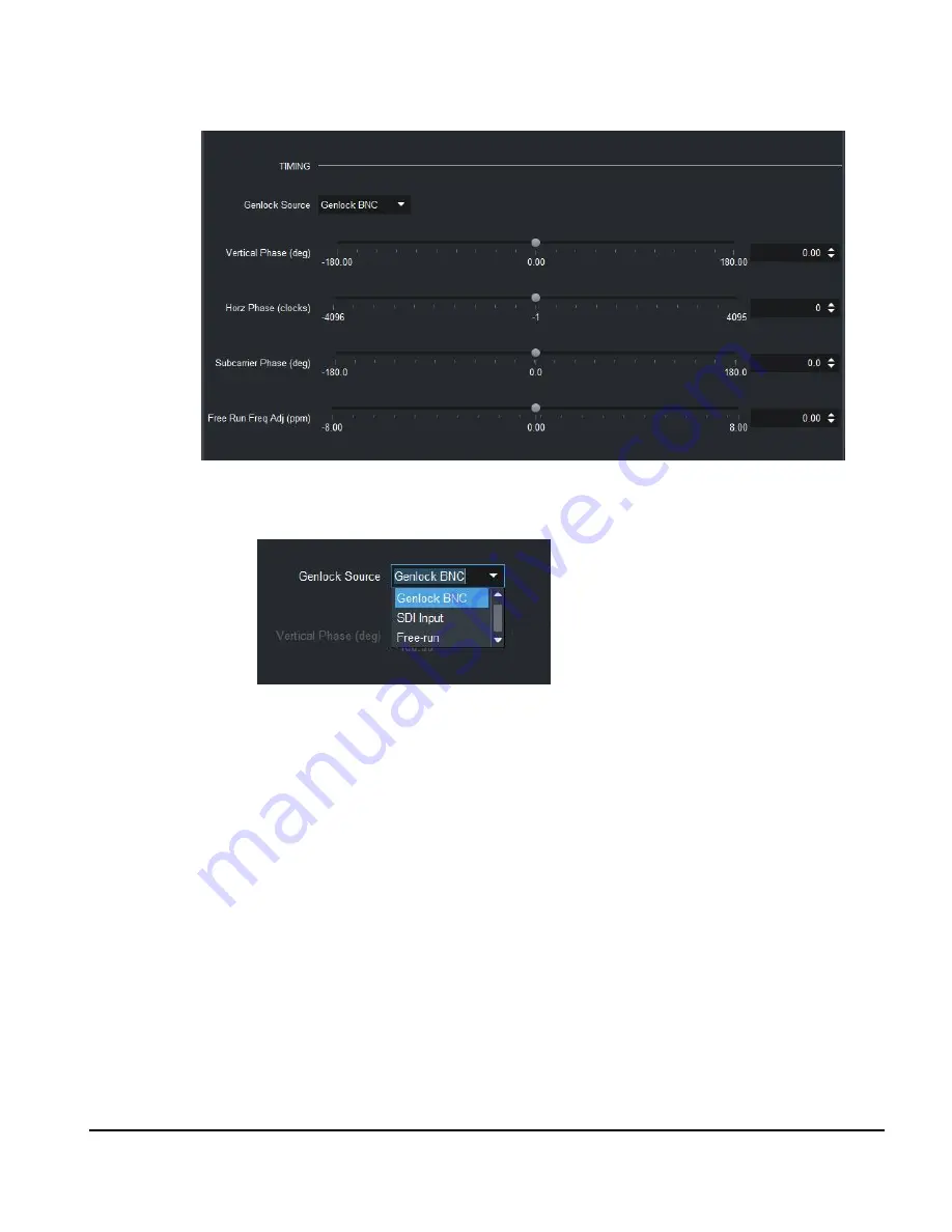
Use the
Genlock Source
drop-down control to choose which signal will be used as the genlock
reference (The Product menu tab indicates the genlock status for the selected reference).
[Genlock BNC] This selection locks the output timing to a reference signal connected to the rear
panel’s
GENLOCK LOOP
BNCs. The reference may be composite sync,
black-burst, tri-level sync, TTL vertical drive, or a TTL frame square wave. The
MVPHD-24 automatically detects the type of signal present.
The Genlock loop input provides a high impedance “loop through” connection
for an external sync reference. The reference signal may be daisy chained through
several MVPHD-24s, or other equipment requiring external sync. If the unit is
the last piece of equipment in the chain, then the unused BNC will require a
termination.
[ SDI Input ] This selection locks the output timing to a serial digital signal at the SDI input.
This allows the MVPHD-24 to lock to a HD camera’s SDI output signal.
Note, the SDI input must be either a 270 MHz (SD), 1.485GHz (HD), or 2.97GHz
(3G) serial digital signal.
[ Free Run ] This selection ignores all genlock input references, and free-runs the output timing
of the MVPHD-24 (see
Free Run Freq Adjust
menu below).
If a signal is not present at the selected source, the MVPHD-24 automatically goes into free-run.


