© Allegion 2013
Printed in U.S.A.
19102 Rev. 12/13-f
3
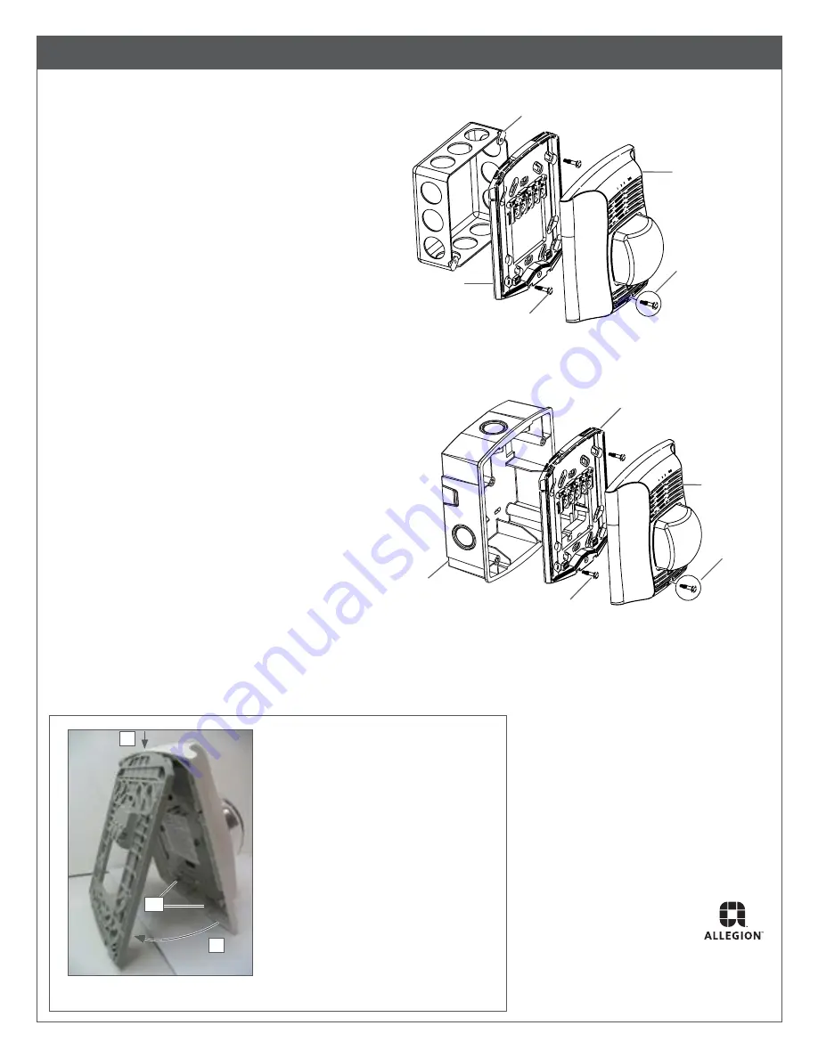
Mount the horn strobe.
Flush Mount
a.
Secure flush mount plate to 4” back box with two #8-32 x 3/4” screws.
b.
Complete field wiring.
c. Attach the horn strobe assembly to the mounting plate. Refer to
Figure 6.
d. Secure horn strobe assembly with the captured screw*.
Horn
assembly
4” back box
recessed in wall
Flush mounting
plate
#8-32 x 3/4”
screws
Captured
screw*
Figure 4, Flush Mounting
Surface Mount
a. Secure surface mount back box to mounting plate with two
#8-32 x 3/4” screws.
b.
Complete field wiring.
c. Attach the horn strobe assembly to the mounting plate. Refer to
Figure 6.
d. Secure horn strobe assembly with the captured screw*.
Figure 5, Surface Mounting
Horn Strobe
assembly
Surface mount
back box
Mounting plate
#8-32 x 3/4”
screws
Captured
screw*
*
Captured screw may be replaced with Torx screw
(provided) for tamper resistance.
Screw pack contains: #8-32 x 3/4” screws (4), Torx head screw (1)
1. Lower horn strobe assembly onto the
top of mounting plate.
2. Swing bottom towards mounting plate
until tabs (a) on horn strobe assembly
click into slots on mounting plate.
2
1
a
Figure 6, Attach Horn Strobe Assembly


