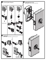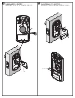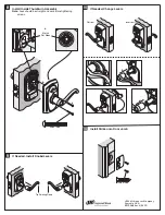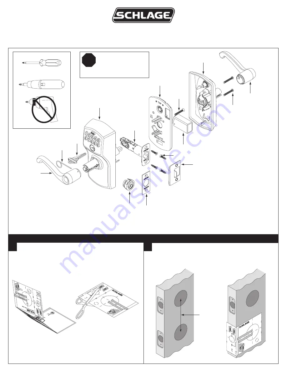
Install Lock
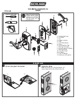
Remove Template From Booklet
1
2
H
A
K
E
D
J
L
M
B
C
F
G
A. Outside Knob/Lever
B. Pin Wrench
C. Key
D. Keypad Assembly
E. Latch
F. Latch/Strike Screws
G. Strike
H. Inside Mounting Plate
J. Mounting Plate Screw
K. Inside Thumbturn Assembly
L. Mounting Screws
M. Inside Knob/Lever
N. 9V Battery
P. Drive-in Faceplate
Q. Square-corner Faceplate
Tools for Installation
OR
2
A.
K
ey
1.
Tur
ns on the b
ac
klight.
2.
Ind
icates lo
ck
status
(pro
gramming
mod
e, l
ow
batte
ry,
etc.
) an
d success
or
failure o
f an ope
ration.
3. Con
fi rms a me
nu ent
ry
du
ring
pro
gramming
(see page 8)
.
4.
Use
d to
exit pro
gramming or to clear
an incorrect entr
y.
B.
Key
pad
1.
Used
to unlo
ck
the lo
ck
by
ente
ring a
vali
d f
our
-digit user cod
e.
2. U
se
d to prog
ram the lo
ck
.
(S
ee page 8
.)
C.
Key
Ov
err
ide
(S
ee
pa
ge
11.)
Use
d to unlo
ck
the lo
ck in the
foll
owing
situations
:
1.
Lo
ck
has
faile
d electronicall
y.
2.
Batte
ry is d
ea
d.
3.
User co
de is not k
no
wn.
D.
Outside
Knob/L
ev
er
T
o minimi
ze
damage
from
van
dalism
,
the outsi
de
kno
b/l
ev
er rotates
but
does
not ret
ract latch e
ven when lo
ck
is
loc
ke
d.
E.
Inside
Knob
/Le
ve
r
The insid
e k
no
b/l
ev
er is al
wa
ys
unlo
ck
ed
for imme
diate e
xit.
FE575
Featu
res
A.
Key
B.
Ke
ypa
d
C.
Ke
y O
ver
rid
e
D.
Outsi
de
Kno
b/L
eve
r
E.
Insi
de
Kno
b/L
eve
r
a
b
2
³⁄₈
” (60
m
m) T
o D
oor
Edg
e
CU
T HE
RE
2
³⁄₄
” (7
0 mm
) T
o Do
or E
dg
e
1⁵⁄₈
"
Fo
r
1
³⁄₈
"
Thic
k Door
For 1
³⁄₄
"
Thic
k Doo
r
⁷⁄₈
”
(22
m
m)
Hole
Templ
ate f
or
FE
575,
FE
595
, BE3
65
For U
se
W
ith
OR
2
¹⁄₈
”
(54
mm
)
Hole
OR
Match
to
D
oor Ed
ge
Door
Edg
e
2
³⁄₈
” o
r 2
³⁄₄
”
Ro
tat
e
Temp
late to
M
atc
h D
oo
r
Installation Instructions
FE595
P515-548
N
Q
P
Check Door Holes
Note:
If door holes do not match template, visit
www.schlage.com for door drilling instructions.
5
¹⁄₂
”
Minimum
Templ
ate
for
FE
575,
FE
595,
BE3
65
2
³⁄₈
” (60
mm
) T
o D
oor
Edg
e
R
ot
a
te
T
e
m
p
la
te
to Match
D
o
o
r
2
³⁄₄
” (
70
m
m) T
o D
oo
r E
dg
e
OR
2
¹⁄₈
”
(54
mm
)
Hole
2
³⁄₈
” o
r 2
³⁄₄
”
Doo
r E
dge
For
1
³⁄₈
"
Thic
k Doo
r
For
1
³⁄₄
"
Thic
k Doo
r
1⁵⁄₈
"
⁷⁄₈
”
(22 mm
)
Hole
For
Use W
ith
OR
Match
to D
oor
Ed
ge
CUT
HERE
Keep the programming
booklet with you while
installing lock. Without
the user codes, you can
get locked out.
STOP

