L
Service Manual
126
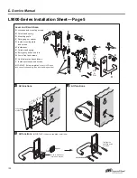
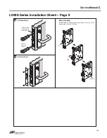
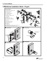
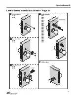
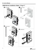
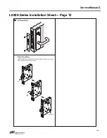
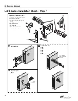
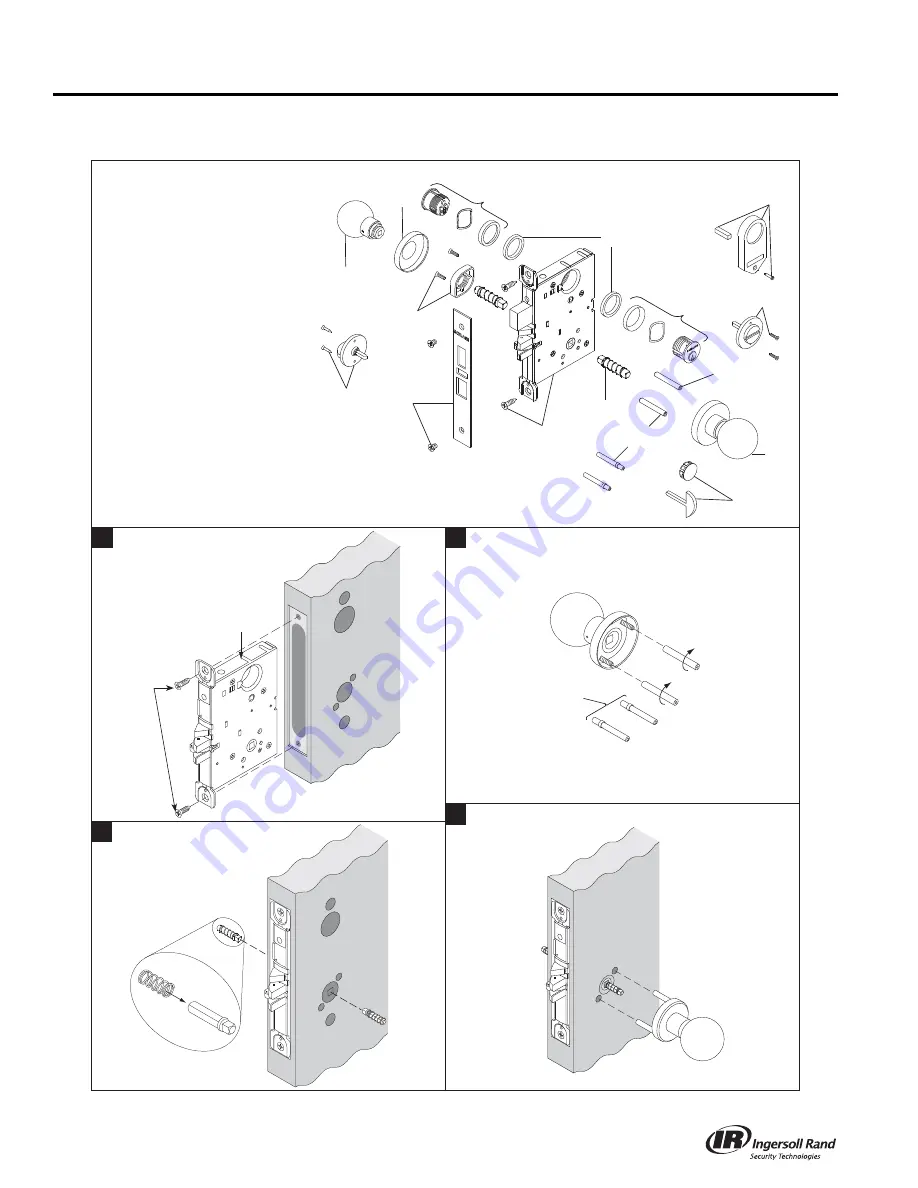
L9000-Series Installation Sheet— Page 9
A
Lockc
as
e
a
nd mo
u
nting
s
crew
s
B
S
pindle
a
nd
s
pring
D
Mo
u
nting po
s
t
s
F
Occ
u
p
a
ncy indic
a
tor
J
In
s
ide th
u
m
b
t
u
rn
K
Cylinder, compre
ss
ion ring
a
nd
s
pring
L
In
s
ide ro
s
e
M
O
u
t
s
ide kno
b
a
nd ro
s
e
N
Emergency t
u
rn
a
nd
bu
tton
P
Coin t
u
rn
Q
Armor front
a
nd
s
crew
s
V
Kno
b
mo
u
nting pl
a
te
W
In
s
ide kno
b
Z
Blocking ring
Knob and Ro
s
e
4
(6QE
x 6
56QE
x 1"
11
3
x 154 x 25 mm
W
Q
A
B
D
OR
O
OU
N
V
M
K
Z
K
L
P
F
J
IMPORTANT:
Before in
s
t
a
ll
a
tion of
a
ny L/LV
S
erie
s
lock,
check lock h
a
nding. (
S
ee door h
a
nding
s
ection.)
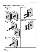
1
All function
s
F
u
lly tighten
a
t
s
tep 9
2
All function
s
OU
T
S
IDE
F
u
lly tighten mo
u
nting
po
s
t
s
on
s
crew
s
4
All function
s
3
All function
s
LV function
s

