Service Manual
L
41
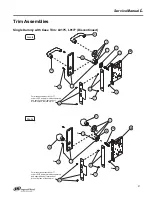
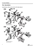
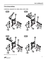
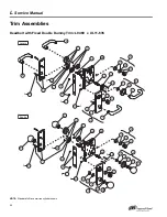
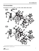
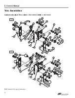
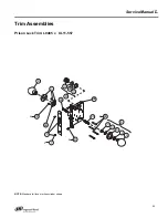
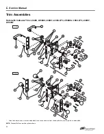
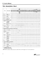
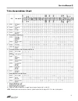
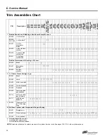
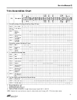
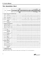
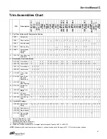
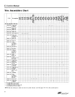
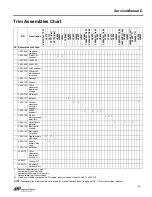
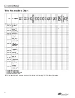
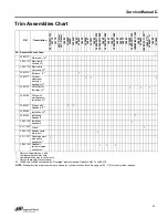
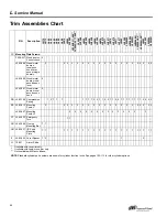
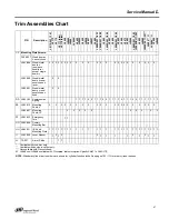
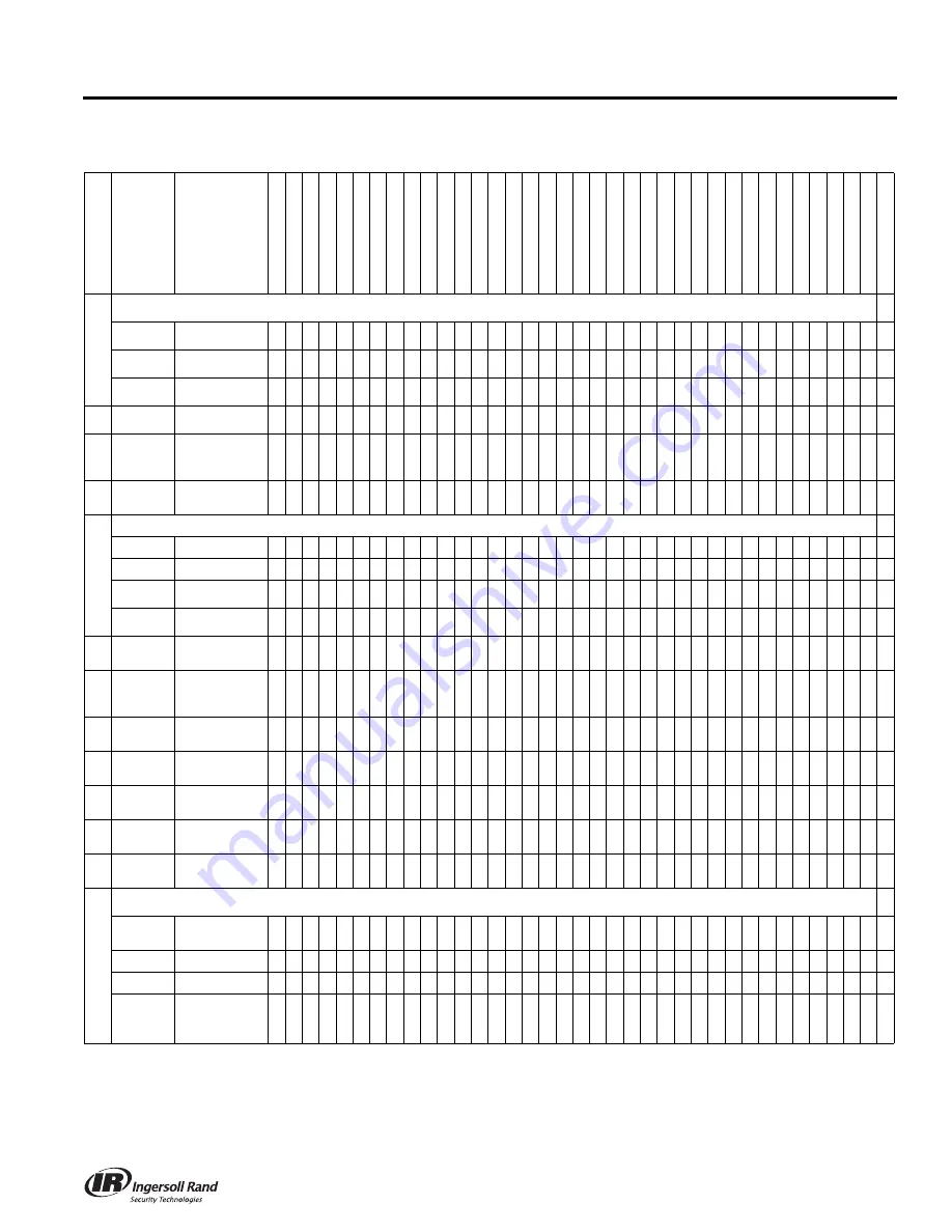
Trim Assemblies Chart
P/N
Description
L
911
0/X
L
1
1-7
41
L9
175
L9
176
L9
177
(d
isc
)
L9
178
(d
isc
)
L9
440
LV
9
4
4
0
L9
444
*
L
V
9
444
*
L9
453
LV
9
4
5
3
L9
456
LV
9
4
5
6
L9
457
LV
9
4
5
7
L9
460
L
946
0/X
L
1
1-6
35
L
946
0/X
L
1
1-8
86
L9
462
L
946
2/X
L
1
1-8
86
L9
463
L9
464
L
946
4/X
L
1
1-8
86
L9
465
L9
466
L9
473
L9
480
LV
9
4
8
0
L
948
2/X
L
1
1-5
43
LV
9
4
8
2
L9
485
LV
9
4
8
5
L9
485
/X
L11
-5
57*
*
L9
486
***
a
L
V
94
86
**
*
a
L9
496
LV
9
4
9
6
O
Full Face Cylinder with Compression Spring:
26-021
Straight cam
30-021
Clover leaf cam
• • • •
2 2
• • •
2 2
• • • •
2
• • •
2 2
• •
• •
30-022
Hotel (handed)
• • •
P
36-082
Blocking Ring
• •
2 2
•
2
2 2
Q
36-083
Compression
Ring and
Spring
• • • •
2 2
• • •
2 2
• • • •
2
• • • • • • • • • • • •
R
C203-736 Case Mounting
screw pack
• • • • • • • • • • • • •
2 2
• • • • • • • • • • • • • • • • • • • • • •
S
Escutcheon Thru-bolts/Screws:
K510-389 N escutcheon
2
2 2
2 2 2 2 2 2
2 2
2
2 2 2 2 2 2 2 2 2 2
L583-120 L escutcheon
2
2 2
2 2 2 2 2 2
2 2
2
2 2 2 2 2 2 2 2 2 2
2 2
L583-133 N escutcheon
2 2 2 2
L583-287 L escutcheon
2 2 2 2
2 2
T
K110-020 Armor screw
pack
• • • • • • • • • • • • • • • • • • • • • • • • • • • • • • • • • • • • •
U
K110-550 Knob Truarc
Rings and
Spacer pack
•
•
• • • • • • • • • • •
• •
•
• • • • • • • • • • • • • • •
V
K510-320 Dummy
Mounting Plug
W
K510-330 Emergency
Button
• •
X
L283-030 Lever Truarc
Rings
•
•
• • • • • • • • • • •
• •
•
• • • • • • • • • •
• • • •
Y
L283-031 I/S Lever
Mounting Plate
• • • • • • • • • • • • • • •
• •
•
• • • • • • • • • •
• • • •
Z
L283-040 Lever Spring
Cage
2
2 2 2 2 2 2 2 2 2 2
•
•
•
2 2 2
•
2
2
•
2
•
2
•
2
AA
Spindles & Springs:
L283-060 Spindle and
Spring
2
•
2
•
2 2 2 2 2 2 2 2 2 2 2
2 2
2
2 2 2 2 2 2 2 2 2 2
•
2 2 2 2
L283-064 Double dummy
L283-065 Single dummy
XL11-766 Free spinning
Spindle and
Spring
†
•
†
Not sold separately as a part.
*
Available with rose trim only.
**
Available with knob x rose trim only.
*** Not available with N escutcheon.
a
L9486 and LV9486 available with “Occupied” indicator option. Specify 09-611 x L583-375.
NOTE:
Standard cylinder part numbers are shown for cylinder function locks. See pages 103–113 for other cylinder options.

