L
Service Manual
2
Introduction
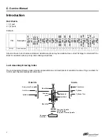
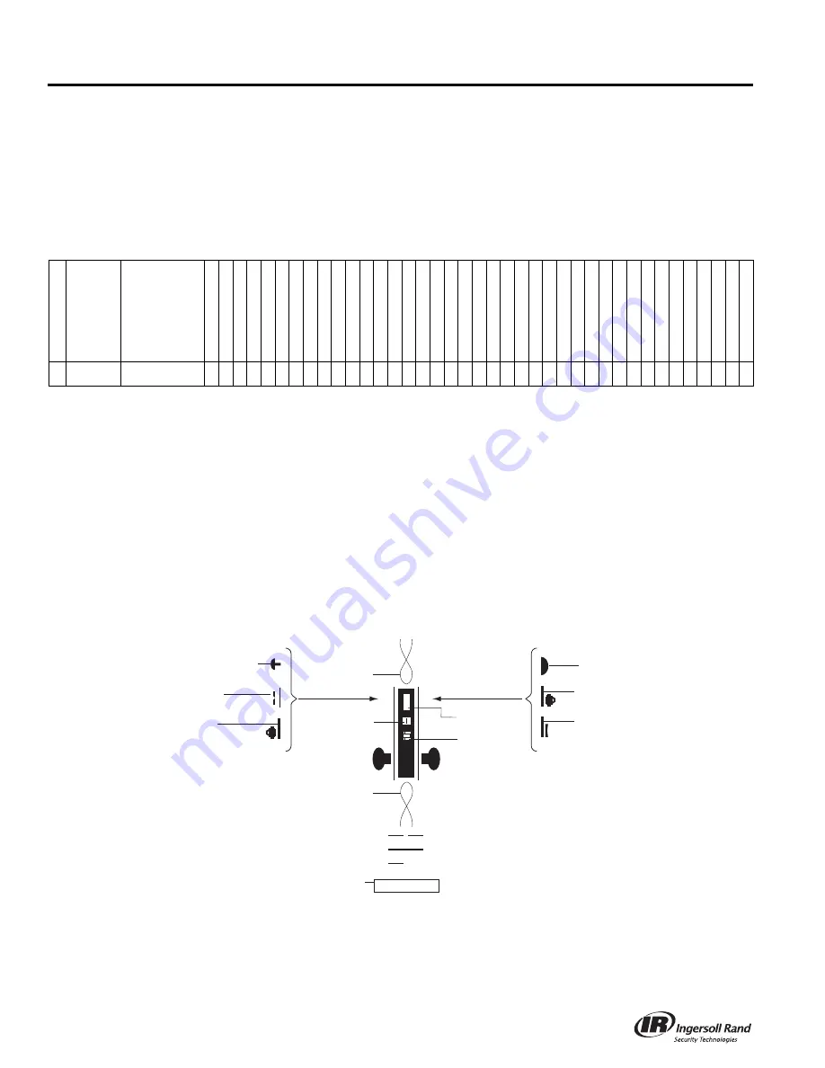
Dot Charts
•
= (1) part
2 = (2) parts
Example:
All parts shown in dot charts are standard. Additional options may be available. See current Schlage Commercial Price
Book for available options, pricing and ordering procedures.
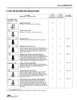
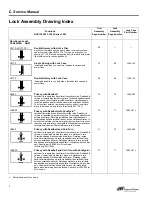
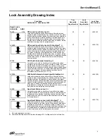
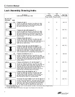
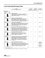
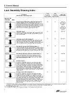
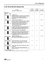
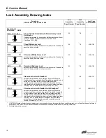
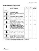
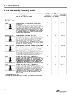
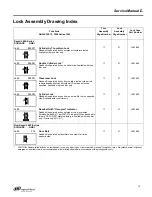
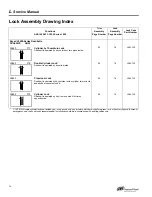
Lock Assembly Drawing Index
The Lock Assembly Drawing Index provides representations and descriptions of available functions. Page numbers for
full trim and chassis drawings are referenced.
P/N
Description
L9
110/XL1
1-741
L917
5
L917
6
L91
77 (disc)
L91
78 (disc)
L94
10 (disc)
L944
0
L
V
9
440
L9444
*
L
V
9
444*
L945
3
L
V
9
453
L945
6
L
V
9
456
L945
7
L
V
9
457
L946
0
L9
460/XL1
1-635
L9
460/XL1
1-886
L946
2
L9
462/XL1
1-886
L946
3
L946
4
L9
464/XL1
1-886
L946
5
L946
6
L947
3
L948
0
L
V
9
480
L9
482/XL1
1-543
L
V
948
2/XL11-5
4
3
L948
5
L
V
9
485
L948
5/XL11-5
57**
L
V
948
5/XL11-5
5
7
L948
6***
L
V
9
486*
**
L949
6
L
V
9
496
30-001
Clover leaf cam
•
• • • •
2 2
• • •
2 2
• • • •
2
• • •
2 2
• •
• •
Out
s
ide
In
s
ide
Emer
g
ency Turn
Latchbolt
Coin Turn
Deadbolt
Thumbturn
Cylinder
Auxiliary
Latch
Electrified
Cylinder
Cylinder Turn
Occupancy
Indicator
Two-piece
S
pindle
S
olid
S
pindle
One-piece Out
s
ide
S
pindle
DO NOT DI
S
TURB
Electrified


