Installation Instructions
C
L
LEVER/
STRIKE
3 Di
3 Gi
4 Ji
4 Qi
1 Qi
15/16
DRILL FOR
#12-24
MACHINE
OR OR #12
WOOD
SCREWS
(2 PLACES)
5/32” DEEP
1 Qi
” DEEP
C
L
MPC COBRA
MPC COBRA
MANUALLY PROGRAMMABLE CYLINDRICAL
LOCKING SYSTEM
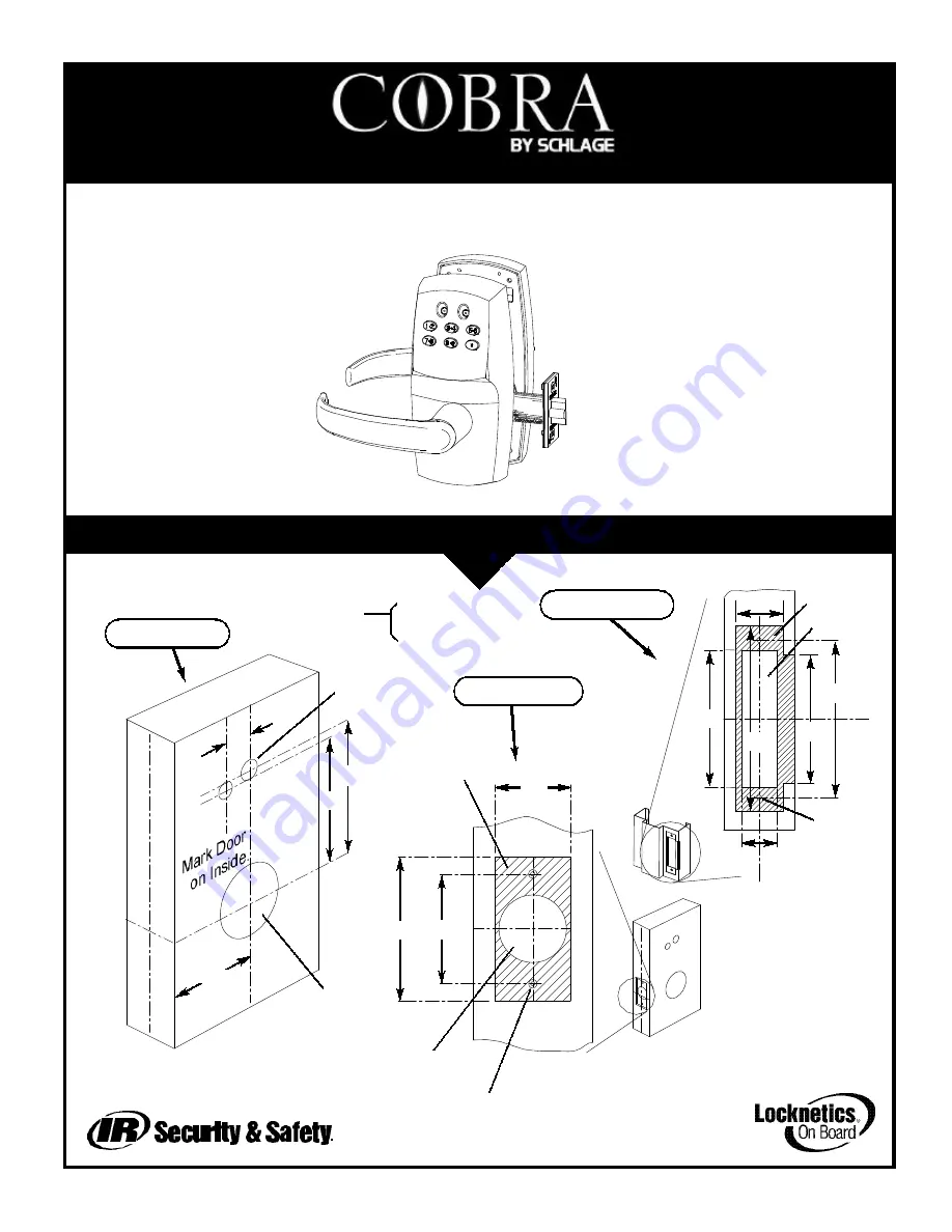
DOOR, LATCH AND FRAME PREPARATION:
11
3 Gi
3 Ji
Ji
BACKSET*
C
L
DOOR EDGE
C
L
LOCK
C
L
LEVER/
STRIKE
DOOR MUST
CORRESPOND
WITH CENTER-
LINE OF
STRIKE
2 Qr
1 iQ
1 Gi
1” HOLE INTO
2
Qi
“ HOLE
2
Qi
“ THRU
19/32”THRU
(2 PLACES)
DRILL FOR #6-32 MACHINE
OR
#6 WOOD SCREWS
(2 PLACES)
DOOR PREP
FRAME PREP
LATCH PREP
*BACKSET
=
2 Di
for OLB
(MEASURED FROM
=
2 Dr
for SLB & ELB
CENTER OF BEVEL)
Use template or information below to prep
door, latch and frame.
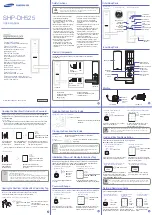
PROGRAMMING STEPS:
INSTALLING 7-PIN SMALL-FORMAT IC CORE FOR MANUAL KEY OVERRIDE:
3/16” DEEP
7
TO CHANGE
PROGRAMMING CODE
ENTER PROG. CODE
ENTER NEW
PROG.CODE
ENTER NEW
PROG.CODE AGAIN
*
*
*
*
33
TO ADD
TOGGLE CODE
ENTER PROG. CODE
ENTER NEW CODE
TO ADD MORE
TO END
*
*
191
*
*
*
*
33
TO ADD
FREEZE/LOCKOUT CODE
ENTER PROG. CODE
ENTER NEW CODE
TO ADD MORE
TO END
*
*
115
*
*
*
*
33
TO ADD
ONE TIME USE CODE
ENTER PROG. CODE
ENTER NEW CODE
TO ADD MORE
TO END
*
*
113
*
*
*
*
99
TO CHANGE RELOCK
TIME DELAY
(DEFAULT 5 SEC.)
ENTER PROG. CODE
TO END
*
*
*
*
33
TO ADD
SUPERVISED CODE
ENTER PROG. CODE
ENTER NEW CODE
TO ADD MORE
TO END
*
*
117
*
*
*
*
33
TO ADD
PASS THRU CODE
ENTER PROG. CODE
ENTER NEW CODE
TO ADD MORE
TO END
*
*
119
*
*
*
*
TO ADD
NORMAL USE CODE
ENTER PROG. CODE
ENTER NEW CODE
TO ADD MORE
TO END
*
*
*
*
*
3
1
1
5
TO DELETE
CODES
ENTER PROG. CODE
ENTER CODE
TO DELETE MORE
TO END
*
*
*
*
*
5
PRESS 1 FOR 1
SEC. AND/OR 5
FOR 5 SEC. THE
TIMES WILL ADD.
Use the steps on this page to
program codes into the lock.
The “*” key is used like the
<ENTER> key is on a com-
puter. After pressing the “*”
key, wait for the red and
green LEDs to stop flashing
before proceeding to the next
step. If at any time the red
LED stays on while the green
LED flashes an error has
occurred. The flashing mes-
sage will repeat three times.
Count the number of flashes
and consult the error code
chart below.
FLASHES ERROR CODE DESCRIPTION
2
Code too long 8 digits max.
3
Memory full, must delete some `
codes
4
Can not delete Programming code -
use Change steps.
5
Second entry did not match first
(Programming Code)
6
Invalid entry, start over. (Verify that
any codes entered prior to this error
do not operate the lock.)
7
Code to be deleted does not exist.
8
Duplicate code, code already exists.
A. HOLD LOCK IN HORIZONTAL
POSITION AS SHOWN AND PUSH
PLUG IN UNTIL PIN FALLS OUT.
REMOVE PLUG.
B. INSERT CYLINDER CON-
TROL KEY INTO CORE AND
TURN CLOCKWISE TO
RETRACT LOCKING PIN.
C. PUSH CYLINDER CORE
INTO LOCK - RESISTANCE
WILL BE NOTICEABLE.
TURN KEY COUNTER-
CLOCKWISE TO ENGAGE
LOCKING PIN.
D. REMOVE KEY.
LOCK IS NOW
OPERATIONAL.
OPERATION:
EITHER THE CYLINDER PLUG
OR THE IC CORE MUST BE
INSTALLED FOR THE LOCK
TO OPERATE. REMOVAL OF
THE CORE OR PLUG AUTO-
MATICALLY UNLOCKS THE
LOCK. IT IS RECOMMENDED
THAT AN IC CORE BE
INSTALLED IN CASE IT EVER
BECOMES NECESSARY TO
UNLOCK THE LOCK USING
MECHANICAL MEANS.
Form 57010 Rev. A
02-22-2002
The MPC Cobra is a battery-pow-
ered manually programmed access
control system. Up to 100 individual
codes can be programmed right at
the keypad. A red and green LED
on the keypad provide visual indica-
tion for programming and access
events. Mechanical key override is
possible when a
7-pin small-format
interchangeable core
(not included)
is installed in place of the cylinder
plug, which comes standard. Either
the plug or the IC core must be
installed for the lock to operate. When the
cylinder is removed (using the cylinder
con-
trol
key) the lock will unlock. Manual key
override should only be necessary if the low
battery output indications have been ignored.
(See Battery Information on page 3). The
design allows for mounting on doors from 1-
1/2” to 2” thick. The retractor design allows
easy adjustment for door thickness by rota-
tion. A shim is available to mount the lock to
a 1-3/8” door. An exterior gasket (EG option)
is available for application to exterior sides of
doors.
Page 1 of 2
Page 4 of 4
REMOVE TAPE
(IF PRESENT)


