background image

Form 57032 Rev. A

01-05-2004

4

VIP 5100 OPEN ARCHITECTURE CYLINDRICAL LOCK

INSTALLATION MANUAL

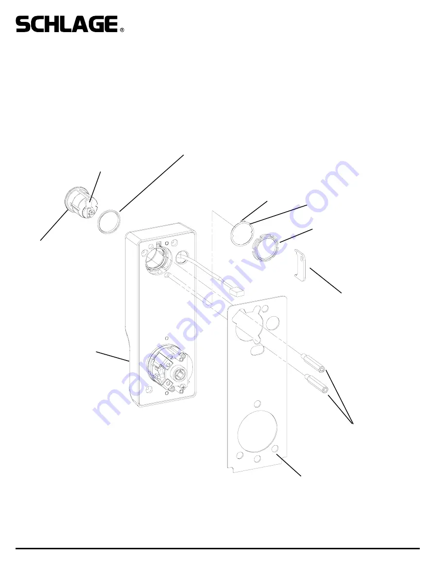
2. INSTALL CYLINDER (IF NOT ALREADY DONE), GASKET AND STANDOFFS:

A. Install cam onto cylinder (if not already done.) Cam must be a straight 11/16” design. See below for recommended cams.
B. Insert mortise cylinder into outside escutcheon from front (keypad/reader) side with keyway down.
C. Slide lock washer onto cylinder (tab on top facing out, as shown below.)
D. Using nut tool (provided) tighten nut onto cylinder.
E. Line up nearest notch on nut with tab on lock washer and bend tab using nut tool so nut is secure. 
F. Install exterior gasket (if used).
G. Install standoffs.

TEST KEY OPERATION NOW: Turning key clockwise until it stops (about 1/2 turn) should allow the lever to turn retractor.

CYLINDER

RECOMMENDED CAMS:
SCHLAGE EVEREST: P/N B502-948
SCHLAGE CLASSIC: P/N B502-191

NUT TOOL

RETRACTOR ASSEMBLY

LOCK WASHER

NUT

STANDOFFS

EXTERIOR GASKET

TAB

NOTE

:

BLOCKING RING REQUIRED FOR CYLINDER
LENGTH GREATER THAN

1-1/8”.

THICKNESS = CYLINDER LENGTH  - 1 1/8”

Summary of Contents for VIP 5100 series

Page 1: ...hes DSM Provides door status via data link to panel interface KSM Provides mechanical key use events via data link to panel interface REX Provides indication of inside lever use for request to exit input via data link to panel interface Options T3 Track 3 card reader data must be ABA track 2 format MG only EXT exterior use option MG only PX model has this standard KD Keyed Different includes Schla...

Page 2: ... the retractor 3 Using appropriate drilling jig and drill bits drill 3 8 or 1 2 wire race from the latch hole through the door toward the hinge side It is not necessary to continue drilling the hole through the hinge side 4 Measure up 3 inches from the center of the 2 1 8 retractor hole and drill a 1 inch through hole on center as shown below 5 Using a 3 8 inch drill bit place the tip of the drill...

Page 3: ... centerlines for the lockset latch and strike C Place template on inside of door opposite the side that the keypad reader will be on Line up the correct reference lines on the template with the edge of the door The centerline on the door should line up with the vertical centerline of the tem plate D Drill holes as described by template DOOR EDGE LATCH FRAME STRIKE DOOR FACE LAY OUT ON INSIDE ...

Page 4: ...top facing out as shown below D Using nut tool provided tighten nut onto cylinder E Line up nearest notch on nut with tab on lock washer and bend tab using nut tool so nut is secure F Install exterior gasket if used G Install standoffs TEST KEY OPERATION NOW Turning key clockwise until it stops about 1 2 turn should allow the lever to turn retractor CYLINDER RECOMMENDED CAMS SCHLAGE EVEREST P N B5...

Page 5: ...signs have an adapter E Re install outside spindle making sure that the round end faces the handle and the spindle is positioned with its edges vertical and horizontal as shown in detail below Note that the cam inside the escutcheon assembly must be positioned such that the dot on it faces the 6 O Clock position see detail below F Rotate retractor and re install it G Change the hand of the handle ...

Page 6: ...LLATION MANUAL 4 INSTALL STRIKE BOX STRIKE AND DOOR SWITCH MAGNET 5 INSTALL LATCH AND DOOR STATUS SWITCH A Install latch into edge of door Be sure to install it with the beveled edge facing door jamb B Install switch as shown passing switch wires through to the inside of the door ...

Page 7: ...utside escutcheon onto door see detail for latch engagement Pass wiring harness through wire hole D Re install latch guard onto retractor 7 INSTALL INSIDE BASEPLATE ASSEMBLY SPACER FOR DOORS LESS THAN 1 3 4 SPACER FOR DOORS LESS THAN 1 3 4 SOCKET CAP SCREW WASHERS DATA POWER WIRES COME FROM HERE IF WIRING METHOD B WAS USED PASS THE WIRES THROUGH THIS HOLE IF A SPACER IS USED DRILL A HOLE IN THE SP...

Page 8: ...de lever to make sure that latch retracts fully IMPORTANT See PIB manual for additional connecting instructions SHIELD DATA B DATA A GROUND V 1 0A 12VDC 0 5A 24VDC OUTSIDE MAIN HARNESS CONNECTION OFF PARKED ON TERMINATION RESISTOR 1 LOCK ADDRESS SEE CHART 2 LOCK ADDRESS SEE CHART 3 ALWAYS SET TO OFF 4 ALWAYS SET TO OFF 5 OFF FAIL SECURE FSE ON FAIL SAFE FSA 6 OFF ALL MG LOCKS ON ALL PX LOCKS 7 NOT...

Page 9: ... escutcheon assembly onto inside baseplate using four screws IMPORTANT 1 MAKE SURE THAT INSIDE SPINDLE IS INSTALLED 2 PLUG REX SWITCH IN TO BOARD 3 DO NOT PINCH WIRES BETWEEN PARTS 10 SEE PIB MANUAL AND SYSTEM PANEL MANUAL FOR SET UP PROCEDURES INSIDE SPINDLE PLUG REX SWITCH INTO PC BOARD DO NOT PINCH WIRES FOR REX SWITCH BETWEEN PARTS ...

Reviews: