background image


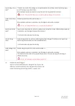
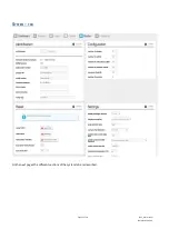
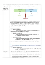
Identification 


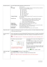
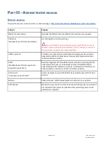
Identification and allocation information 
of the device 

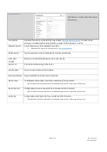
unit address 

Address of the device on the databus (see chapter 

Schleifenbauer databus

).  Number can be 

between 1 and 65535 (When using Modbus, number can be between 1 and 247). 

firmware version 

Current firmware version installed on the PDU. 

Please check the website for the latest version: 

www.schleifenbauer.eu


SPDM version 

The actual version of the Schleifenbauer Products Data Model. 
 

sales order 
number 

Reference of initial Schleifenbauer sales order number. 
 

product ID 

Product identification tag of the device. 
 

serial number 

Unique, sequential production number. 
 

hardware address  Unique identification of the device controller. 


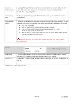
device name 

 Configurable device name, which has a maximum of 16 characters. 

Note: this field is not connected with the “extended name support” and is always max 16 characters 


device location 

Configurable location name, which has a maximum of 16 characters. 

Note: this field is not connected with the “extended name support” and is always max 16 characters 


vanity tag 

Configurable vanity tag, which has a maximum of 20 characters. 

Note: this field is not connected with the “extended name support” and is always max 20 characters 


Page 32 of 58 

 V262_User manual  

Schleifenbauer PDU 

Summary of Contents for V2.62

Page 1: ...V2 62 Schleifenbauer PDU User manual...
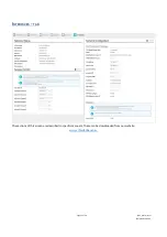
Page 2: ...clamps 10 Cabling the PDU ethernet databus and sensors 11 How to connect the PDU to LAN 11 How to connect a databus 11 How to connect sensors to a PDU 11 How to connect a NO NC contact on Classic PDU...

Page 3: ...language 21 How to enlarge a pane in L sized screens 21 User interface 22 How to change and save settings in the web interface 22 Dashboard tab 23 System status 23 Load 25 Interfaces 26 Sensors tab 2...

Page 4: ...irmware Using SPST 50 How to upgrade the firmware Using USB 51 Schleifenbauer databus what is it 52 How to prevent data losses because of cable cuts Ring redundancy 53 How to create a databus using Sc...

Page 5: ...oblems It is not necessary to read the complete manual W HAT S NEW Added choice of DHCP hostname serial number or sysname Added locate function that blinks PDU display at request Added devicetype read...

Page 6: ...by using Schleifenbauers customization tool when ordering I NTERFACES There are several interfaces integrated in the PDU In the Admin section of this manual you will find information about the Interf...

Page 7: ...blue 05 red 06 yellow Not shown but also available is enclosure color natural Note actual colors may vary Measurement Unit Remark Energy kWh total subtotal Voltage V with voltage dip registration Curr...

Page 8: ...the Netherlands NEN 1010 The voltage maximum permitted current and the number of phases must be correct This information is displayed on the front side of the PDU The maximum permitted power must be...

Page 9: ...g brackets or are delivered separately if they have been ordered separately the installation manual one per shipment Please note that the PDU User Manual can also be found online at http schleifenbaue...

Page 10: ...wide cabinet it is necessary to create additional space for airflow This can be done by using the sunken installation brackets Because of the shape of the bracket it is possible to partially sink the...

Page 11: ...ion ports One is marked as sensorport the other two as databus ports in and out The left databus port is the incoming databus port The right databus port is outgoing This is a MUST HAVE for devices in...

Page 12: ...s shown in the image below How to connect NO NC contact on a G3 PDU 3rd generation PDUs and DPMs are equipped with a USB port and are able to operate two NO NC dry switch contacts Note that on a PDU o...

Page 13: ...an lead to the formation of condensation in the PDU if this guideline is not followed Please keep in mind that the maximum allowed temperature for a metal enclosure is 70 C for installation in a norma...

Page 14: ...Firmware for Classic PDUs are in the FW1xxx range 2 This option is called Local alert reset and must be activated through the interfaces 3 USB port on g3 generation 3 only to be used for firmware up...

Page 15: ...ity or the status of the NO NC contact Actions press any button to stop blinking for a short period blinking will stop so you can read the display resetting the alert can be done by pressing both scro...

Page 16: ...mple input page Note Input x shows the name of the Input This information can be configured from the Web Interface Inputs tab or from the other interfaces Example outlet page The scroll buttons allow...

Page 17: ...ype value The sensor type is indicated by a letter The letters are abbreviations for the sensor type as follows For all optional sensors see www schleifenbauer eu DS status of NO NC contact O open C c...

Page 18: ...ling our customers to set up an RC monitoring system that prevents dangerous situations inside the datacenter Where to measure residual current When monitoring residual current at a single location it...

Page 19: ...e your link local address which will always start with FE80 the second and third will be your LAN and WAN address respectively In the IP Interfaces display you can find information about the device mo...

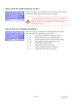
Page 20: ...e found at downloads on the Schleifenbauer website In the About page you can also find information regarding serial number product information and Schleifenbauer order number ID unique hardware addres...

Page 21: ...l to configure the PDU This chapter gives an overview of the different possibilities Login By default the web interface is enabled To navigate to the web interface the IP address and port number can b...

Page 22: ...ion to the PDU serving the webinterface With multiple connections open the network traffic on the serving PDU and any PDUs connected through the databus will increase while response time will decrease...

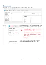
Page 23: ...he last alert In this example there is an outlet overcurrent at outlet number nine When enabled Auto reset alert alerts will be automatically cleared after the chosen time without active alert conditi...

Page 24: ...external power supply 64 Controller error A hardware error has been detected 128 Slave reset A communication issue has been detected with an outlet slave module temperature alert 1 Temperature alert r...

Page 25: ...e indicated 0 OK 22 means that there was a current drop at outlet 22 input current drop alert 1 Input current drop alerts occur due to a sudden current drop for an input When multiple inputs are in al...

Page 26: ...t threshold the bar will be green The alert threshold is visualised as a yellow vertical line See also chapter System tab Settings However when the load passes the alert threshold the bar will turn re...

Page 27: ...me option enabled the name field can contain 18 characters See also chapter System tab Settings type Shows the sensor type This is detected automatically See also chapter Operating the PDU description...

Page 28: ...otal reset Total amount of energy per line since the last reset This value is reset by unlocking and clicking the reset button power VA Apparent power per line power W Real power per line PF Power fac...

Page 29: ...l System tab Settings kWh total Total amount of energy per line value cannot be reset during the lifetime of the devices subtotal reset Total amount of energy per line since the last reset This value...

Page 30: ...ate Shows the configured or actual outlet state depending on the hardware model There are several possibilities See Unlock at the end of this table For devices built from February 2018 on the displaye...

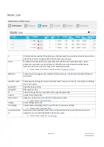
Page 31: ...S YSTEM TAB On the next pages the different sections of the system tab are described Page 31 of 58 V262_User manual Schleifenbauer PDU...

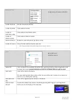
Page 32: ...uct ID Product identification tag of the device serial number Unique sequential production number hardware address Unique identification of the device controller device name Configurable device name w...

Page 33: ...alerts are reset restart CPU This is a reboot of the controller of the PDU After restarting all alerts and peak registrations will be erased Be assured power distribution will NOT BE INTERRUPTED durin...

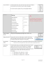
Page 34: ...e mounting orientation of the PDU itself It can be set as peak duration msec Configurable time in milliseconds a current overload is allowed to occur before an alert is given Note we advise to prevent...

Page 35: ...state by respecting the fixed system wide outlet delay use individual outlet delay at power up all the outlets are set to their last known state but delayed by the individual outlet delay plus fixed s...

Page 36: ...characters setting is valid for SNMP the web interface and the LCD display for API and Modbus both the original and extended name registers can be simultaneously and independently used when the device...

Page 37: ...I NTERFACES TAB The sections of this screen are described in specific manuals These can be downloaded from our website www schleifenbauer eu Page 37 of 58 V262_User manual Schleifenbauer PDU...

Page 38: ...e the SPBUS Schleifenbauer Products BUS protocol into their custom software solutions SPAPI Schleifenbauer Products application programming interface Describe a high level API for SPBUS devices such t...

Page 39: ...ettings checkbox to edit the snmpv3 settings When finished click the save user button A classic PDU without an ethernet connector that is running on firmware 1 xx doesn t have a device type register A...

Page 40: ...e on the bottom of this page shows a properly closed ring It s closed by connecting the out of the last device in the ring to the in of the first device A closed ring guarantees redundancy of all data...

Page 41: ...password for each profile initially equals the username of the profile For example the default password for the admin user profile is admin Each user can change all more restricted user passwords in a...

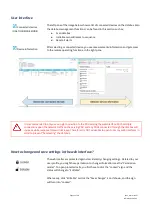
Page 42: ...horized access In the tab Interfaces section User management passwords can be changed There are five login profiles 1 Viewer viewing only 2 User viewer resetting alerts and switching outlets 3 Power u...

Page 43: ...the default These options are available in the Interfaces section of the web interface Custom hostname Change the hostname value save and restart PDU Schleifenbauer prefix and sysname Add custom name...

Page 44: ...y sending router solicitation packets via ICMP6 using its link local address This means that a IPv6 enabled router must be available on the network and it must send ICMP6 router advertisement packets...

Page 45: ...nterfaces In section network configuration is a drop down box called IP Protocol select The default value of this drop down box is IPv4 only To enable IPv6 set this to either IPv6 only or IPv4 IPv6 du...

Page 46: ...and the prefix to a number between 0 and 128 will limit the allowed IP scope to the network the PDU is connected to Filtering will then be disabled IPv6 example Setting a filter of A76F D222 12FF FEB...

Page 47: ...ted The TLS cipher suites are listed in the following format example TLS_DHE_RSA_WITH_AES_256_GCM_SHA384 1 TLS prefix 2 Key Exchange algorithm DHE Excluded for static keys 3 Authentication algorithm R...

Page 48: ...A MBEDTLS_TLS_ECDH_ECDSA_WITH_AES_128_CBC_SHA256 MBEDTLS_TLS_ECDH_ECDSA_WITH_AES_128_GCM_SHA256 Note on self signed certificates At the moment only self signed certificates are supported Certificate G...

Page 49: ...reboot the PDU to actualize your new configuration How to send SNMP Traps with IPv6 The PDU allows the user to set two SNMP trap destinations Traps occur when an alert has been triggered in the PDU T...

Page 50: ...ly During the upgrade process the power distribution won t be interrupted Our firmware firmware tools and manual can be downloaded from our website and can be used for free When a Schleifenbauer Gatew...

Page 51: ...settings section at the web interface Alternatively it is possible to enable or disable the USB interface with the Modbus or SNMP interface Download the latest firmware from https docs schleifenbauer...

Page 52: ...on are separated in the Schleifenbauer PDU All operations on the databus do NOT interfere with the distribution of power to the connected equipment in the racks Advantages of the databus easy to build...
Page 53: ...fect the readout or control of the PDUs it will try to get access through the alternative route on the ring A cable cut is detected by our firmware and an error message will be submitted to the databa...

Page 54: ...ateway blue lines in the image In a closed databus ring the Gateway is able to reach all connected devices through IN and OUT databus ports clockwise and counter clockwise Advantage one IP address mak...

Page 55: ...different Schleifenbauer devices can be connected in a ring which makes the system easily scalable to customer needs It is advised to close the databus ring Connect the last device in the databus to...

Page 56: ...settings have been changed restoring IP access may be required The following procedure causes the PDU to adopt various default values which allows it to be redetected on the network without losing an...

Page 57: ...ashboard appears Check the Inputs tab and notice the peak current of 8 30A in this example image Clear the alert locally or by the reset button in the Reset section in the System tab the peak current...

Page 58: ...e contact us in case there are questions regarding our products T 31 73 5230256 F 31 73 5212383 E mail support schleifenbauer eu Website http schleifenbauer eu If an email is sent a case is created au...

Reviews: