


Index
Reference Manual |Edition 4.0 (10-2013) |EcoCut 3300
105|108
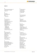
INDEX
A
Accident prevention regulations 9
Actual value not in range 56
Adapter 46
B
Battery 75
Binding position 42
Blade area 60
Blade
- blocked 56
C
Classifications 15
Cleaning interval 60
Commands 11
Commercial cleaning agent 61
Commissioning 29
Communication error 56
Component 65
Compressed air 61
Connection cable 79
Connector
- HotStamp 80
- Prefeeder 79
Control contact 80
Cross references 11
Cutting axis-clamping pin 42
D
Daily maintenance 60
Danger zones 27
Defective component 65
Devices 45
Diagnostic 55
Dimensions 19
Display 35
Display gap setup 23
D-sub connector 79
E
Ejection time 42
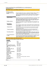
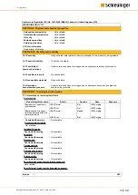
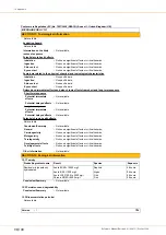
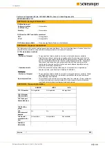
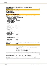
Electrical specifications 83
Electromagnetic interference 82
Electrostatic discharge 82
Emergency stop link 16
Entry keys 35
Entry screen 38
Errors 59
F
Fault localization 55
Feed speed 40
File not found 56
Function keys 35
Fuse holder 25
G
Gap setting wheel 23
Ground potential 80
Guidelines 11
H
Hot stamp 25
Hotline 59
HotStamp timeout 56
HotStamp/PreFeeder 25
I
Iguana 77
Inductive load 81
Inspection 59
Installation regulations 29
Intended application 14
Interface connection cable 13
Interior 61
Invalid name 56
L
Language 47
Liability for damage 11
Lift up wire end switch 23
Lubricating grease 13
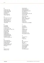
M
Machine name 59
Machine serial number 78
Magnifier 10
Main menu 39
Main power switch 25
Mains connection 25
Maintenance 59
Marking 53
Marking device 49
Marking time 26
Menu level 10
Menu screen 38
Motor switched off 57
Summary of Contents for EcoCut 3300
Page 8: ...Table of contents 8 108 Reference Manual Edition 4 0 10 2013 EcoCut 3300...
Page 22: ...4 Product specifications 22 108 Reference Manual Edition 4 0 10 2013 EcoCut 3300...
Page 74: ...12 Spare parts exploded view drawings 74 108 Reference Manual Edition 4 0 10 2013 EcoCut 3300...
Page 76: ...13 Decommissioning disposal 76 108 Reference Manual Edition 4 0 10 2013 EcoCut 3300...
Page 102: ...14 Appendix 102 108 Reference Manual Edition 4 0 10 2013 EcoCut 3300...
Page 103: ...Personal notes Reference Manual Edition 4 0 10 2013 EcoCut 3300 103 108...
Page 104: ...Personal notes 104 108 Reference Manual Edition 4 0 10 2013 EcoCut 3300...
Page 107: ......
Page 108: ......


